 Muth
MuthUsually dot matrix displays use shift register, demux, counters to scan the column while driving the rows. In the most multiplexed option, only 2/3 timing and one data lines are needed. A frame sync, a column clock and a pixel clock. Then the pixel data is synced one by one. Resulting a rather high frequency toggling on the data line.
I would like to try to send the data 8 by 8, so for a 100Hz refresh rate, instead of 409.6KHz, it gives 51.2KHz. Doing so will reduce the logic components needed as well.
Before going further, I would like to test driving the anodes 8 by 8. The circuit to generate the 360V pulse need to charge a small capacitor, and my little power supply had to handle the current peak to charge them 8 by 8.
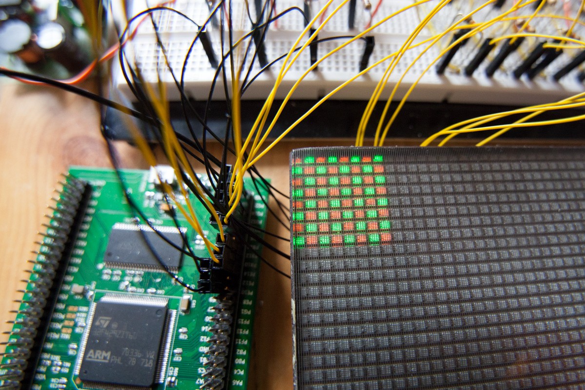
So I cabled 8 anode drivers on the breadboard but had to use the FMMTA42 SMD transistor for 4 cathodes as I didn't have enough MPSA42 transistors. I tried the timing parameters as if the all screen is driven. To summaries, the cathodes are switched one after the other at a 156us rate (100Hz * 64), then wait 10ms as if the screen is at 100Hz. And the 8 anodes are charged during a 8th of that time as there will be 8 block of 8 pixel to drive per cathode.
I think it needs some adjustments, mostly because I forgot here to introduce a small pause between the cathode switch. It results that some pixels are flipped with a small delay. However, it seems to be promising for more pixel driving.
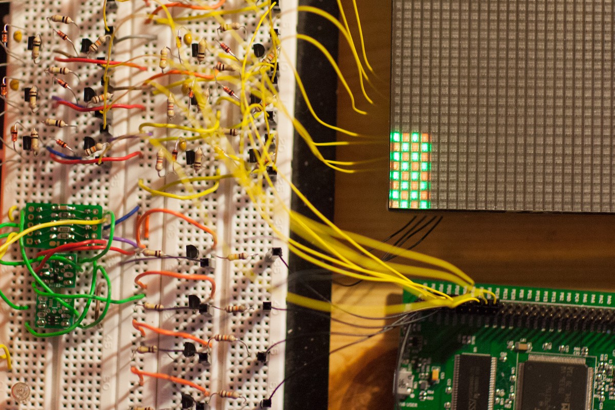
The brightness could be improved by increasing the refresh rate, but I faced unstable pixel ignition. It is maybe due to a too short time to charge the capacitors.
Besides, the brightness is correct, below is in a room with the direct sun luminosity (3:00pm):
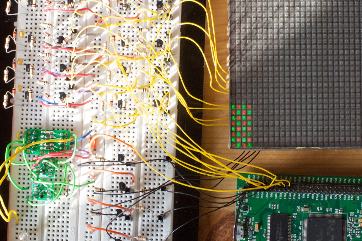
And then the same with two light bulb:
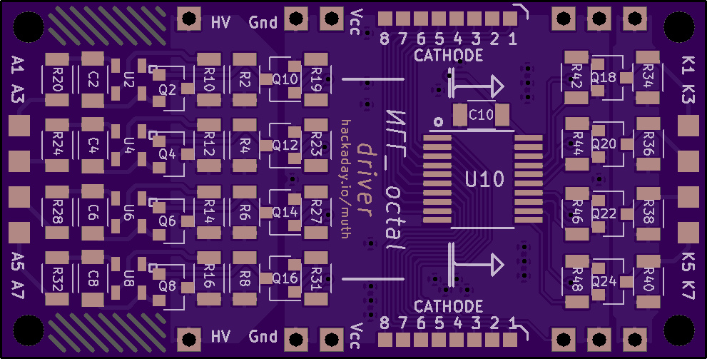
I spent few hours to draw a small PCB to drive 8 anodes and 8 cathodes. I've just put a logic buffer in order to have a 'chip select' line. That way I can quickly drive a full screen with 32 GPIO. It's a lot but doable with a microcontroller. The aim is to check rather easily if this driving strategy is valid before continuing. If it's working I can keep the 8x8 driver PCB and think about a more efficient logic.
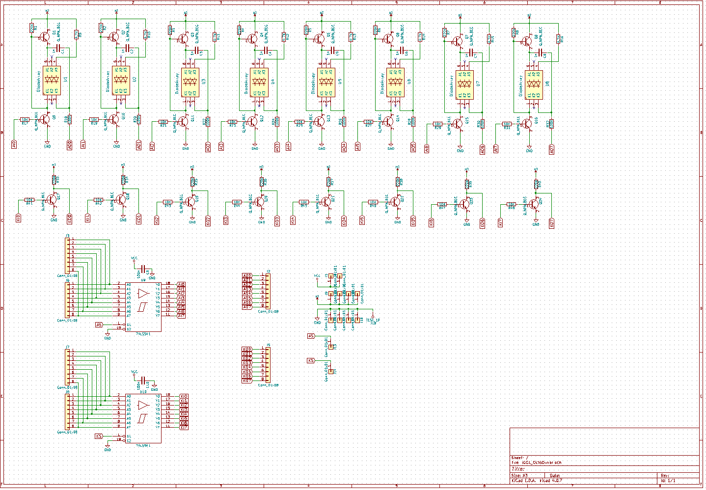
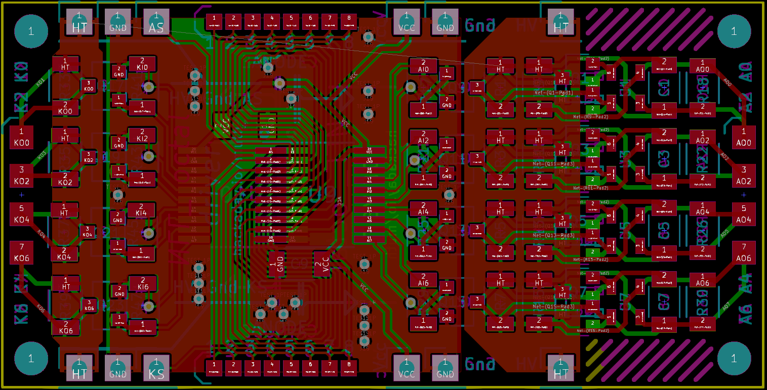
The buffers are 74HC541, transistors are FMMTA42, diodes are BAS21VD. And the Kicad source is here : https://github.com/pierre-muth/IGG_-64x64M/blob/master/IGG1_OctoDriver.zip
And I've ordered them on OSHPark : https://oshpark.com/shared_projects/6yxoDPPP
Now I have to be patient !
Discussions
Become a Hackaday.io Member
Create an account to leave a comment. Already have an account? Log In.
Nice job
Are you sure? yes | no
Thanks ! Will see in ~two weeks if no spark appears !
Are you sure? yes | no