 marcelclaro
Diabetes mellitus is a global problem, in 2013, 382 million people have diabetes worldwide, most with more than 45 years, and global economic cost in 2014 was estimated to be $612 billion USD. The future projections are not encouraging. 
All forms of diabetes increase the risk of long-term complications (cardiovascular disease, blindness, chronic kidney desease, etc.), however, the complications of diabetes are far less common and less severe in people who have well-managed blood sugar levels.
Today, the diary glucose level check can be done at home, nervertheless, its need a little drop of blood and a chemical reaction strip. So, this check becomes painful and expensive (each strip could cost 0.33 USD). These drawbacks decrease the patient adhesion to treatment.
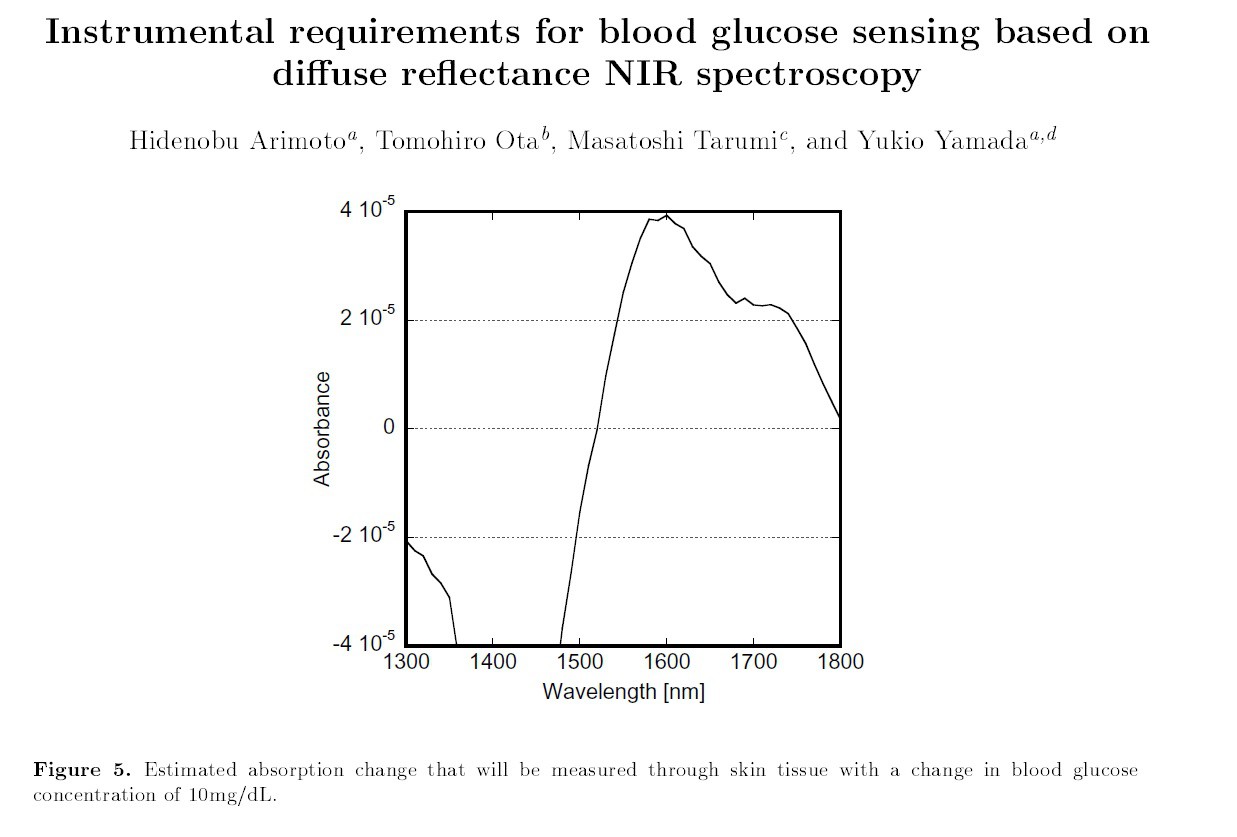
I propose a glucose meter design based on light absorbance of glucose that already been extensively studied and sucessful applied in laboratory scale.
However, until now, the comercial (FDA approved) glucose meters still using blood samples or cost hundred, thousands of dollars.
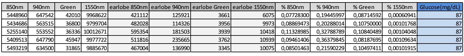
Two challenges are found in construction of this type of device: calibration data and ultra-low-noise absorbance measurements. Raw data is not a problem to me, as a diabetic type 1, I have more than 4 measurements per day, which I can trust and use.
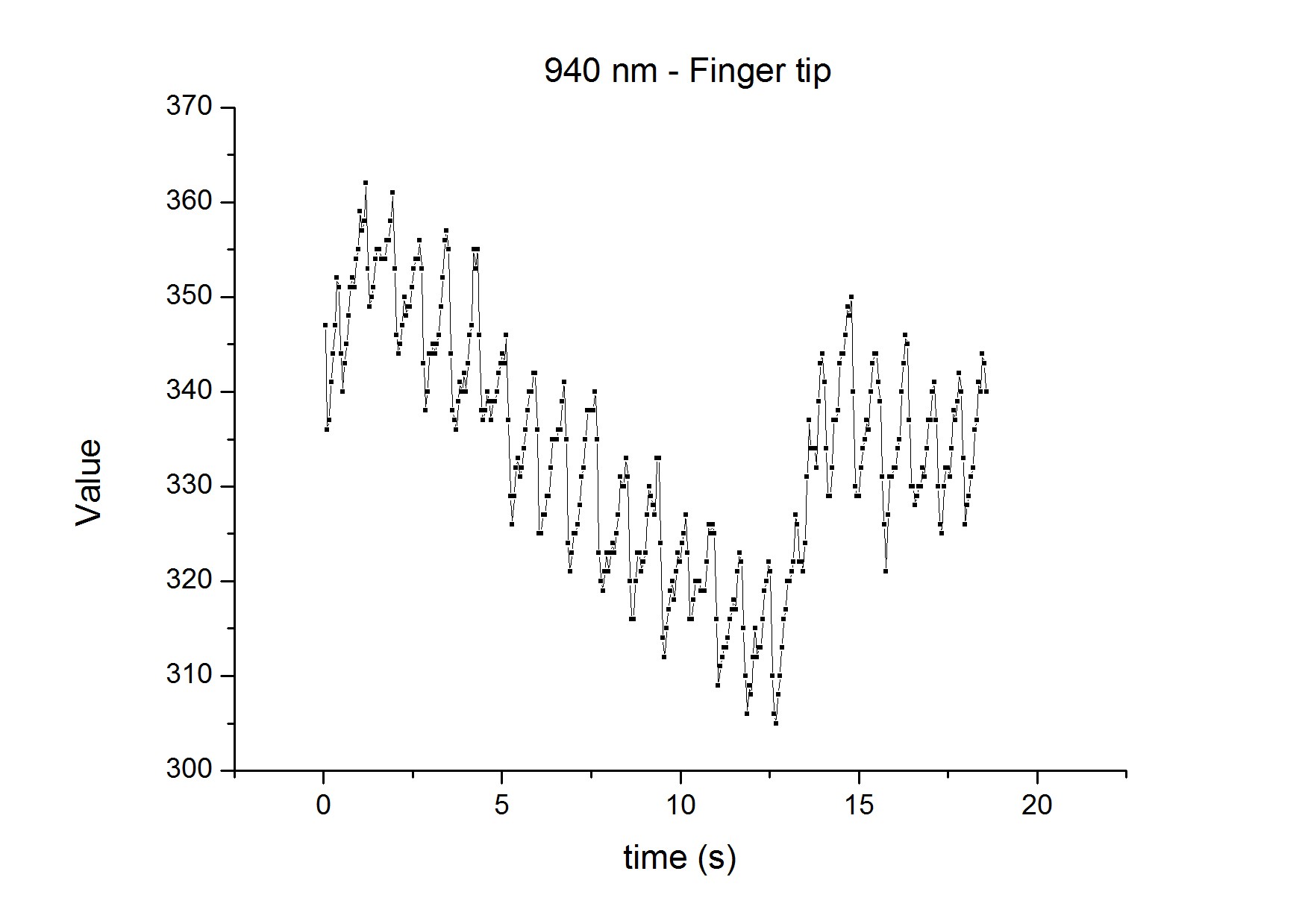
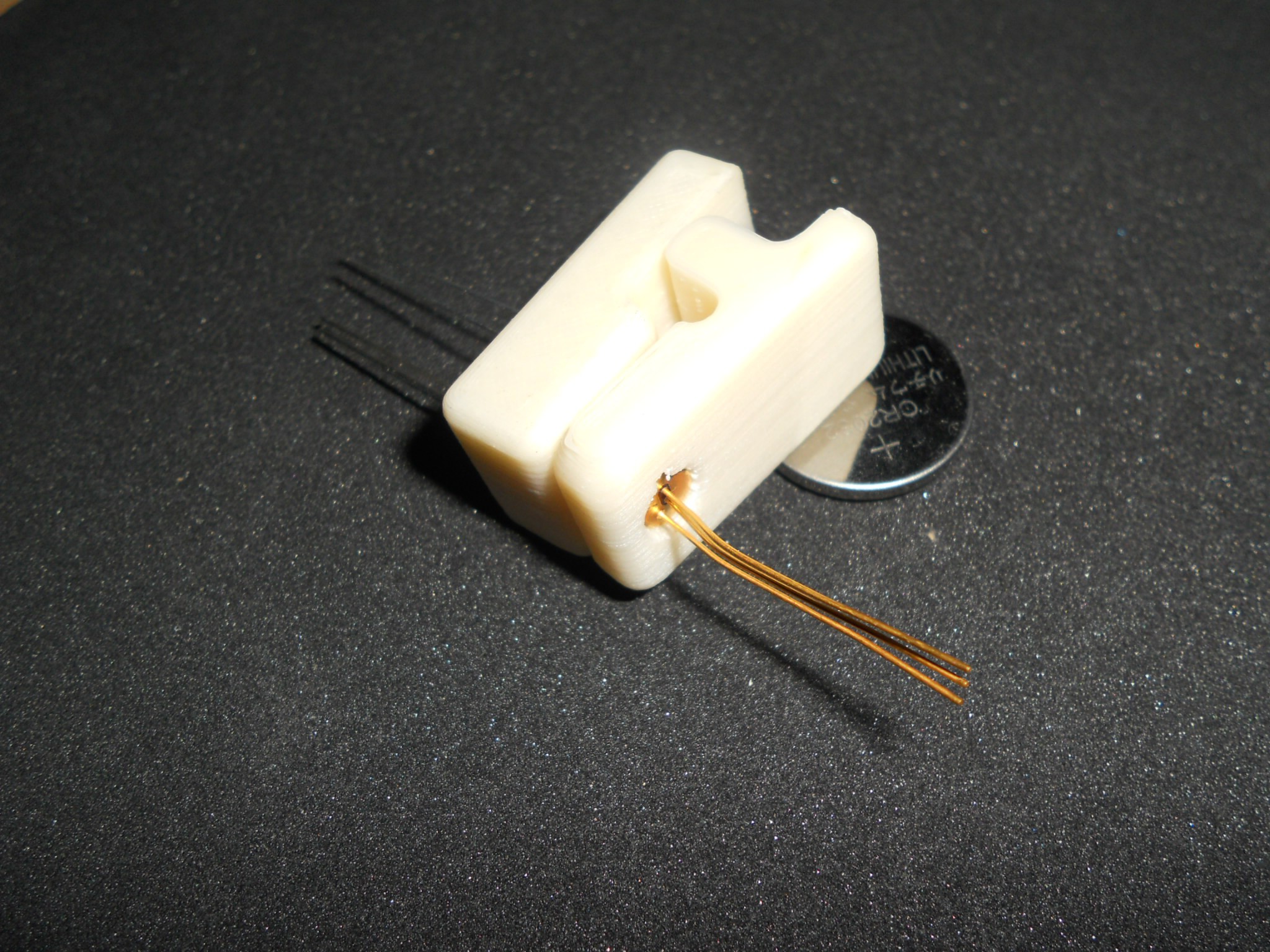
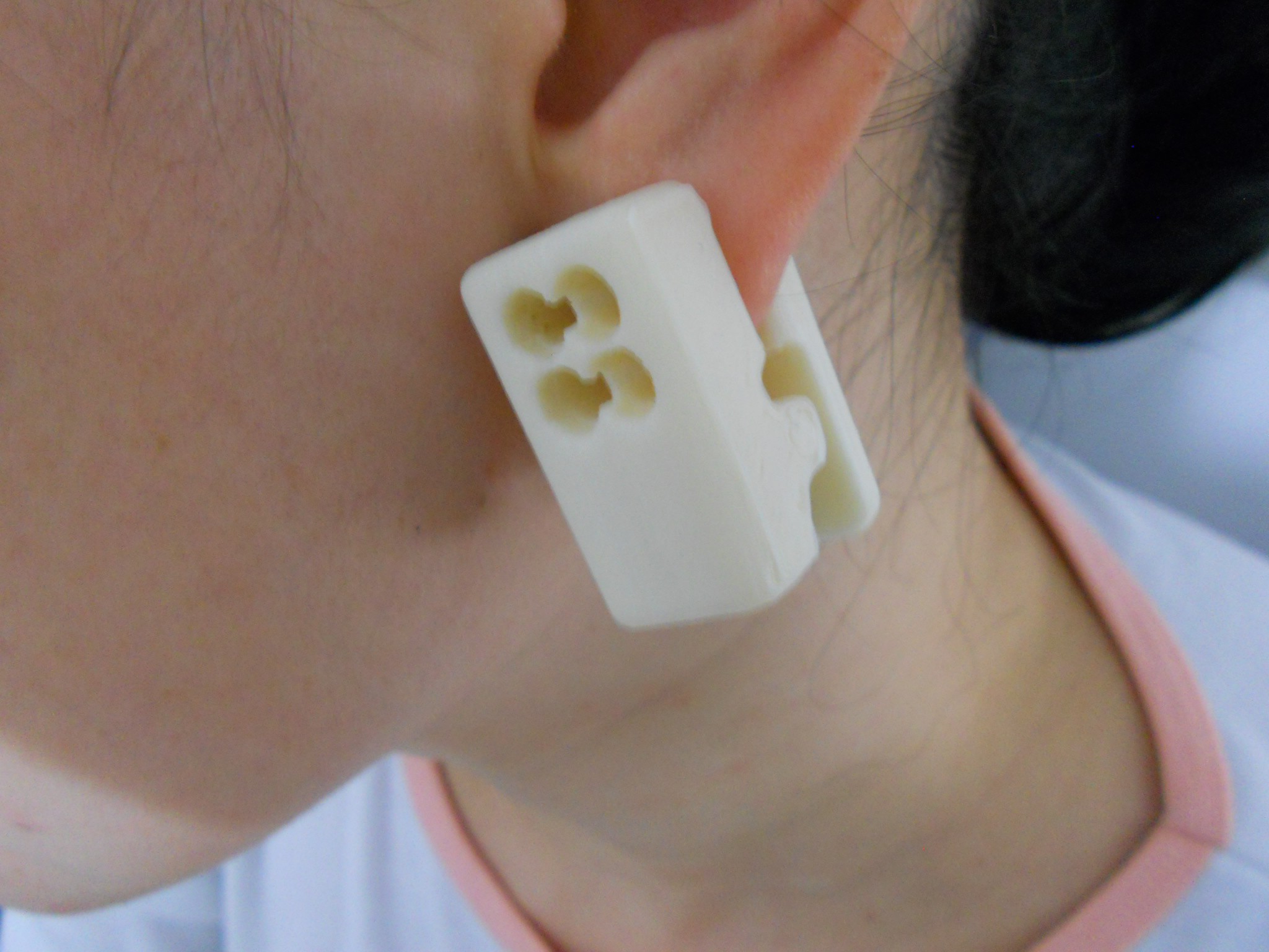
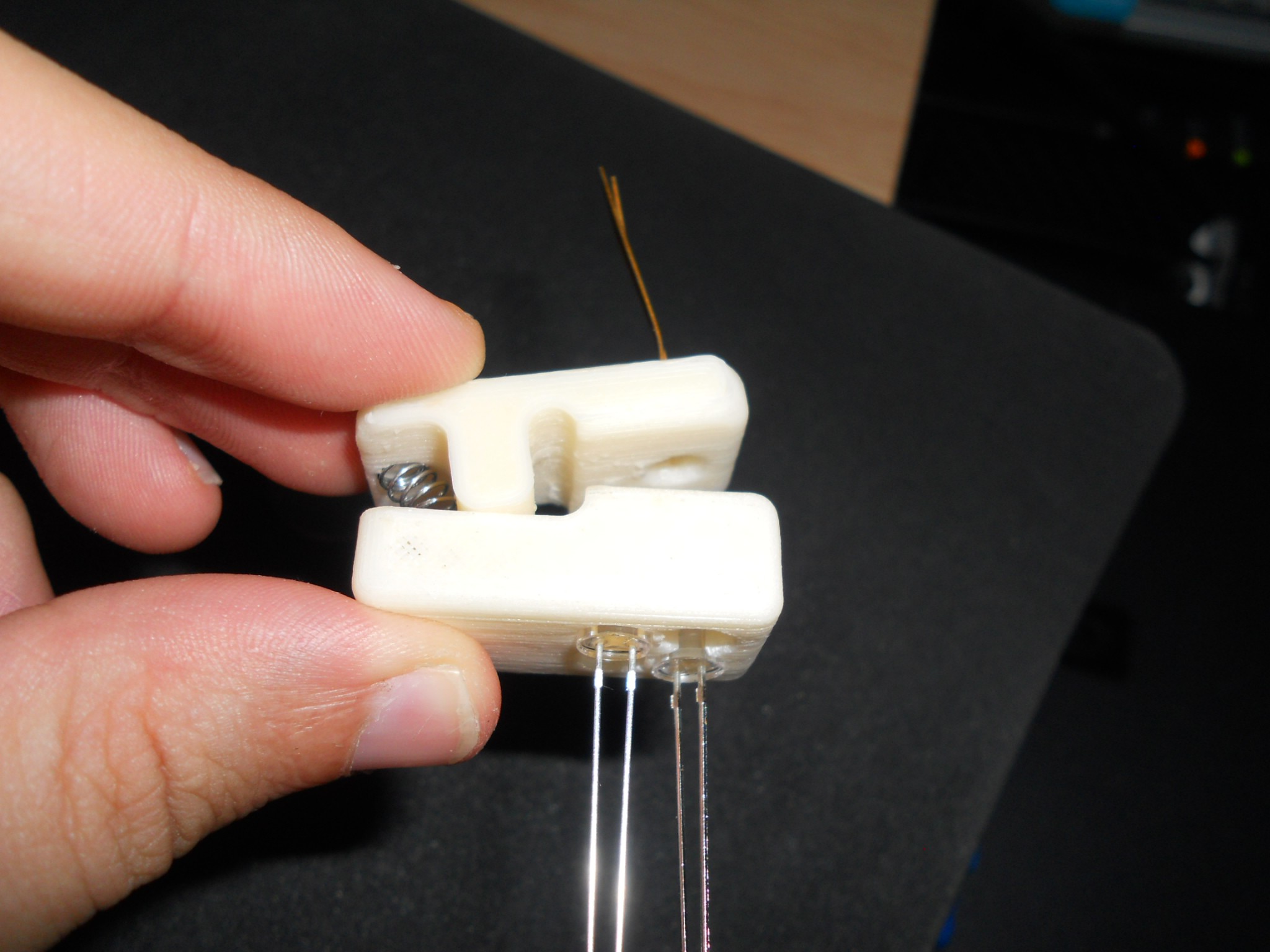
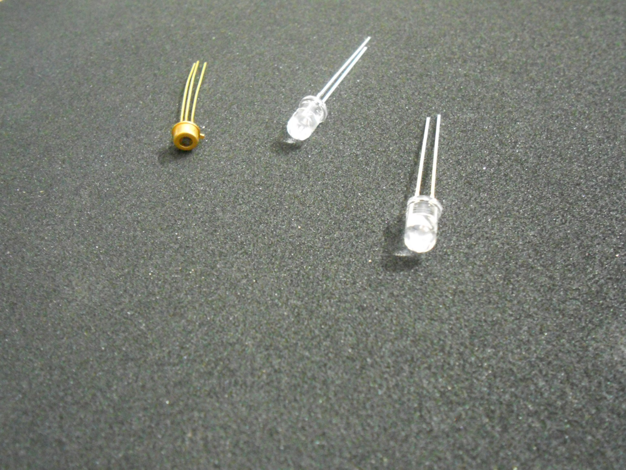
The big challenge is therefore how to build a precise sensor but keeping it small and cheap. I think that using very large integration time and simple InGaAs PIN diode we will be able to reach the necessary precision.
Complementary wavelenghts (850 and 940nm) are a good source of information about water and blood quantity.
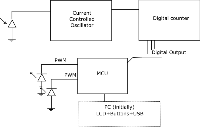
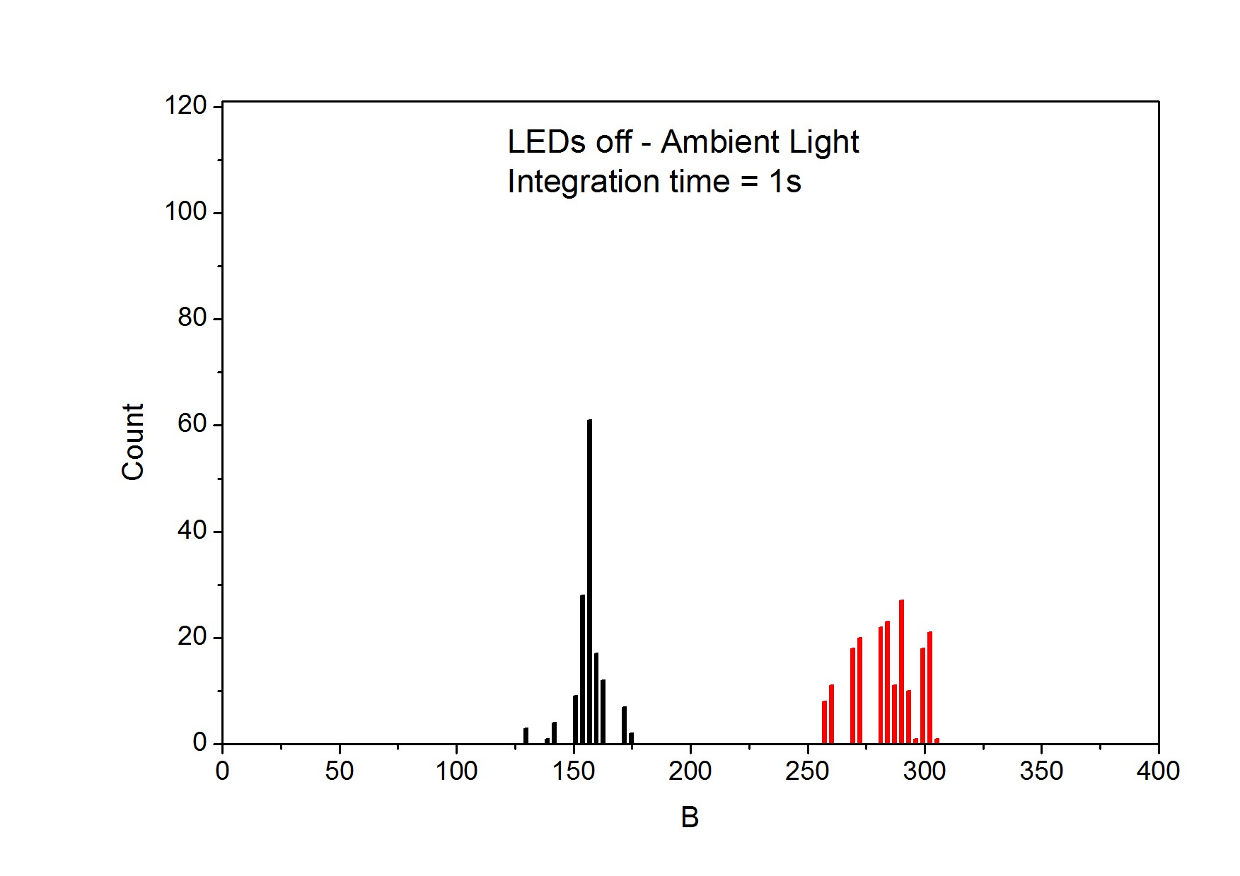
Since traditional capacitive transimpedance amplifier suffer from saturation and integration time problems, another ADC aproach will be used. With a current controlled oscillator (CCO) and a digital counter, the integration time will be limited only by digital counter output register, and we will far from expensive high resoluton ADCs.
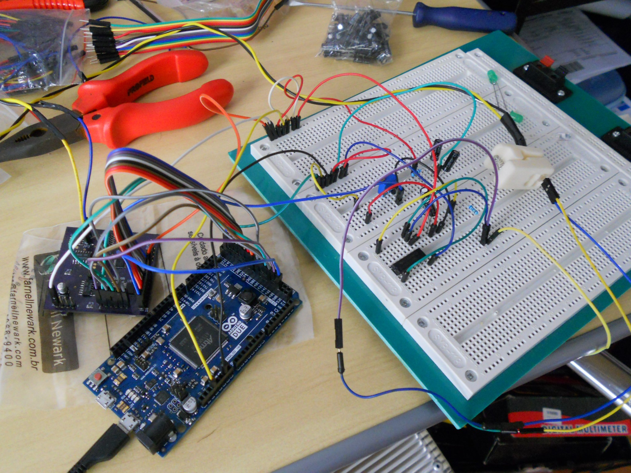
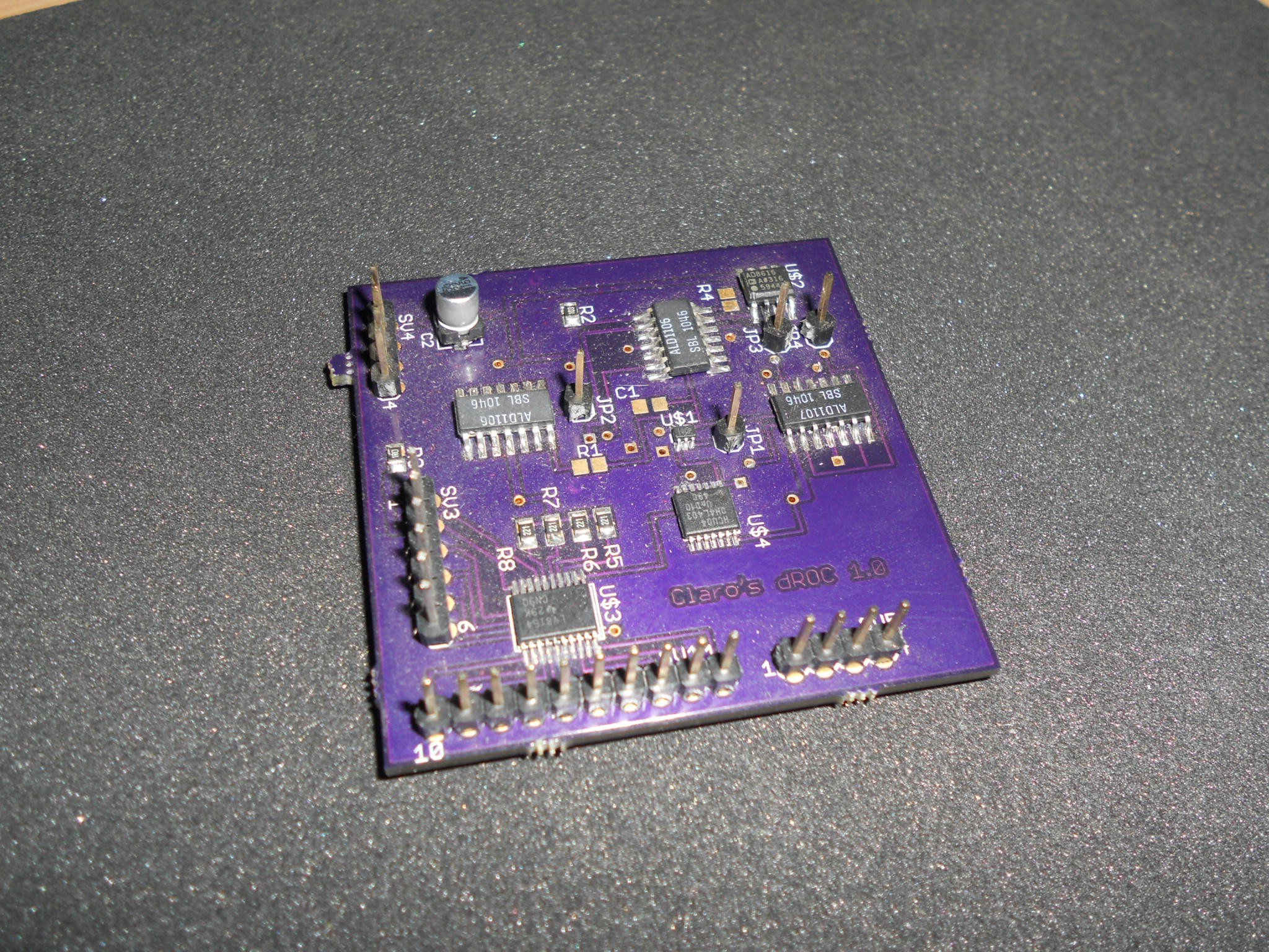
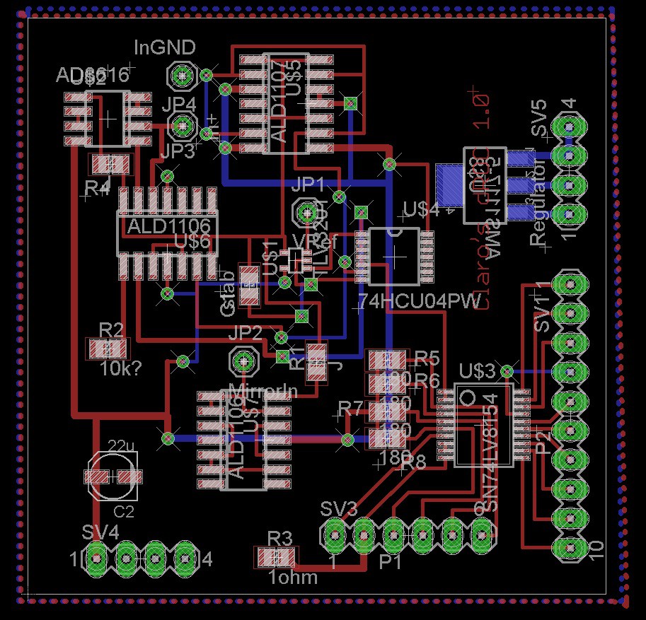
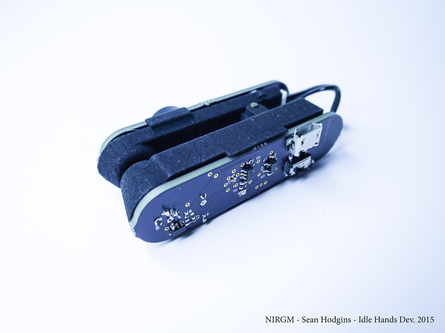
The general design is presented below:
Initially, the couple tlv3201 (comparator) and sn74lv8154 (counter) was chosen to provide a 32bit counter for less than 1$.
I did not find one good CCO IC yet. So, I will try to make my very own oscillator
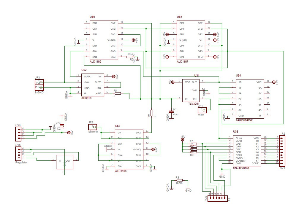
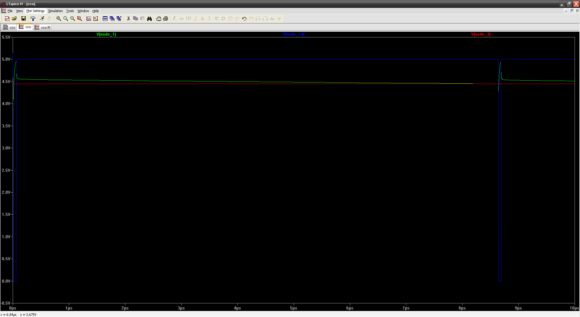
The op-amp (AD8616) and transistors(ALD1106 and 1107) will cost less than 2$ each one. And the funcionallity was confirmed by SPICE simulations.
It's time to make PCBs!!!!


 Dominic
 Ultimate Robotics
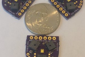
 Kris Winer
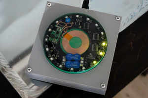
 Scott Clandinin
Nice! Following your project!