 Ted Yapo
Here's the first cut at a schematic for the game console.
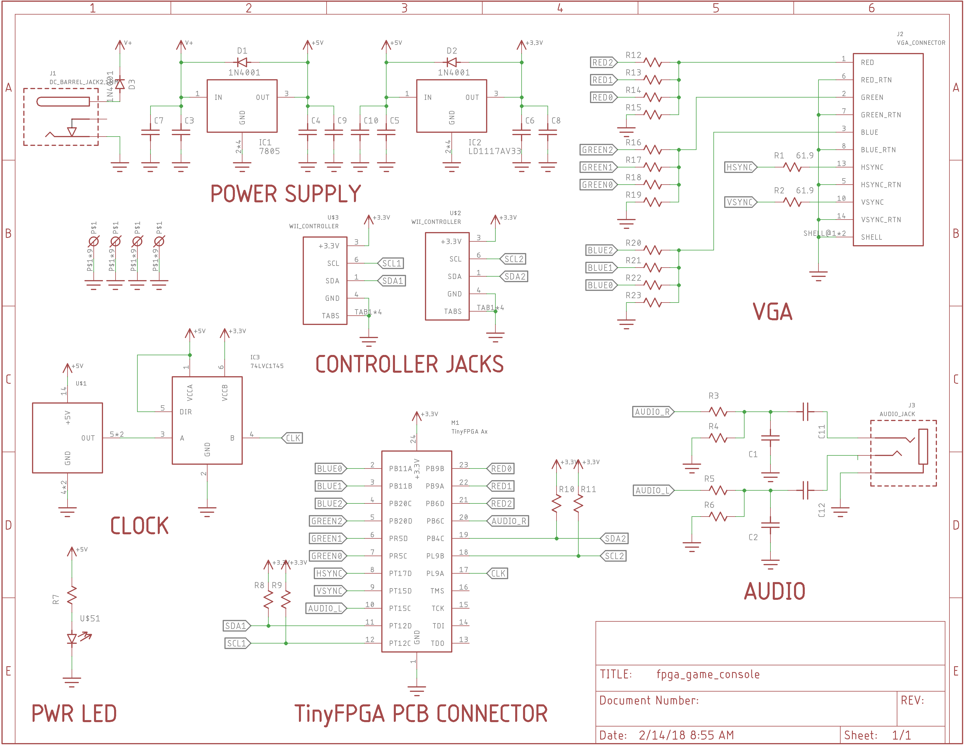
The PCB will have a socket to accept either an A1 or A2 TinyFPGA board. There are sites on the PCB for either an 8- or 14-pin metal can crystal oscillator. I chose a through-hole oscillator since 25.175 MHz oscillators (640x480 @60Hz VGA) don't seem to be widely available in SMT. Additionally, when using an A2 board as brains, you are free to choose a different oscillator frequency from your junk bin and use the internal PLL to synthesize the correct dot clock. I've experimentally used 640x480, 800x600, 1024x768, and 1280x1024 with the internal oscillator on the A1, and would have gone higher except that's the maximum resolution of my test monitor.
Since most metal can oscillators are 5V, a 74LVC1T45 level translator provides a 3.3V output. I didn't see the point in messing with resistive dividers at 25+ MHz.
The VGA output uses three 3-bit weighted resistor DACs. I used similar 2-bit DACs on #PIC Graphics Demo last year, and figured I'd try to push it a little. This will give a 512 color display. The resistance values are chosen to weight the bits correctly, produce a full-scale 0.7V output, and present a 75-ohm output impedance. Similarly, the two sync lines are back-terminated in 75-ohms to damp reflections on the cable.
Audio output is PWM, but there are left and right channels. In #Oscilloscope Vector Game Display I had a look at the output produced by the Raspberry Pi's PWM audio, and it wasn't pretty. It is cheap and easy, however, so I'll take two out of three. Again, the resistors are chosen to produce line-level output (0.894V peak) and 100-ohm output impedance (not critical).
The controllers use Wii nunchuck connectors. A wide variety of retro-style controllers are available for this interface, which uses I2C communication. The MachXO2 devices on the Ax boards have a hard IP I2C port which might make a single-player game possible on the A1, which otherwise would probably be too small. I don't know if the I2C lines are pulled-up in the controllers, so I'll add sites for pull-ups on the PCB, which can go unpopulated if needed.
The PCB is waiting until I receive the parts. The mechanical drawing on the VGA connector datasheet was confusing, and I'm not sure I got it right. I'd rather not add to my collection of coaster PCBs.
Will you be able to program complex games on this? No. The challenge will be coming up with something that fits.
Discussions
Become a Hackaday.io Member
Create an account to leave a comment. Already have an account? Log In.