 Cassio Batista
Despite the improvements achieved by the research community in the area of human-computer interaction, conventional interactions are still the most used ones for device control. However, these methods usually force the use of hands, which becomes a barrier for those who have some problem in performing upper-limb motor movements — including people with problems in fine motor skills, weakness of the fingers, etc., whose limitations are mainly concentrated at handling physical objects. Thus, non-conventional interactions should be explored in order to avoid people with motor disabilities to be digitally excluded. In other words, non-conventional interactions could be used as Assistive Technologies since they might be the only way for those people to autonomously interact with electronic devices.
Adaptive switches, one of the most used devices in the context of Assistive Technology, allow the physically challenged users to activate devices that are usually triggered by conventional buttons or keys, which can be a fundamental aspect at not leaving those people apart from the use of electronic devices. However, these kind of switches usually have a high commercial value and can cost more than U$ 300 USD, such as the Pneumatic Switch, which is a price relatively high to be paid.
According to World Health Organization (WHO) on its book [WHO Global Disability Action Plan 2014-2021], approximately 1 billion people around the world have some kind of disability, and 80% of these people live in sub-developed countries, where their purchasing power is highly influenced by the fragile economies of these countries. A person living in the Brazil, for example, where the minimum wage is R$ 954 BRL (about U$ 244 USD), could hardly buy a Jelly Bean Twist that costs U$ 65 USD, since approximately 26% of that person's income would be compromised.
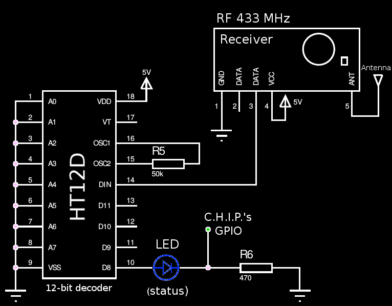
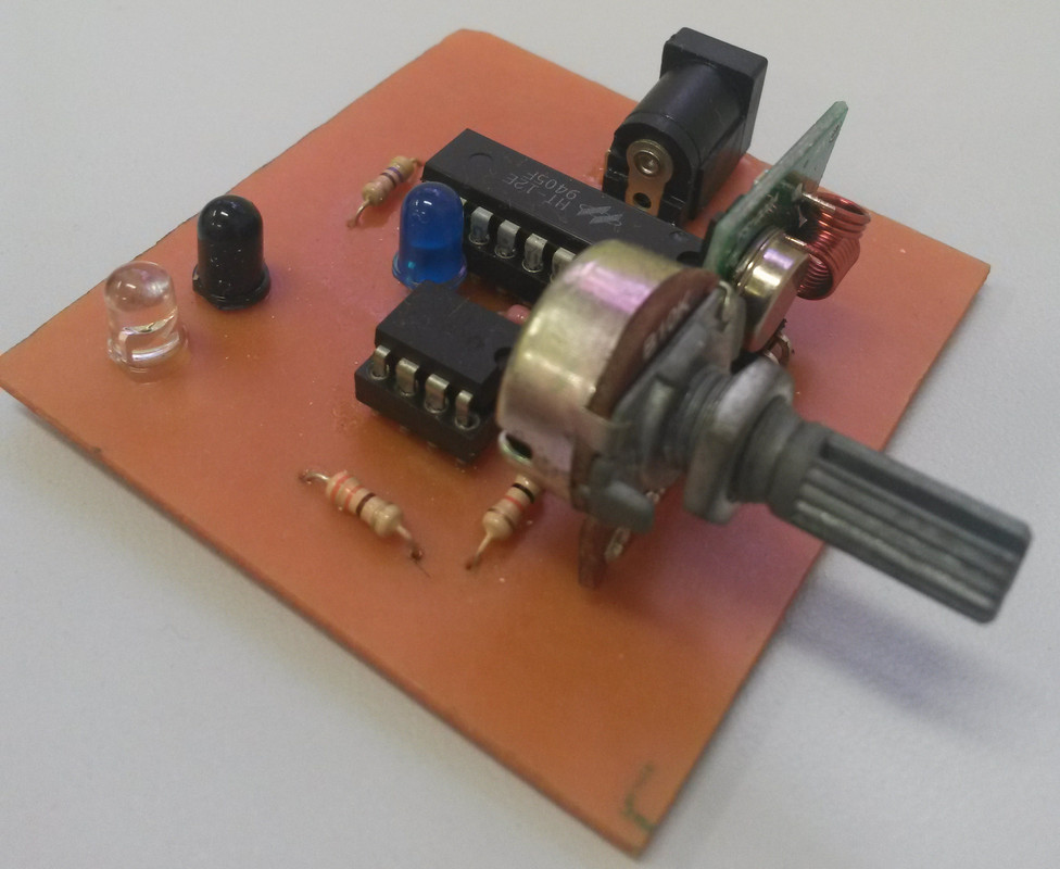
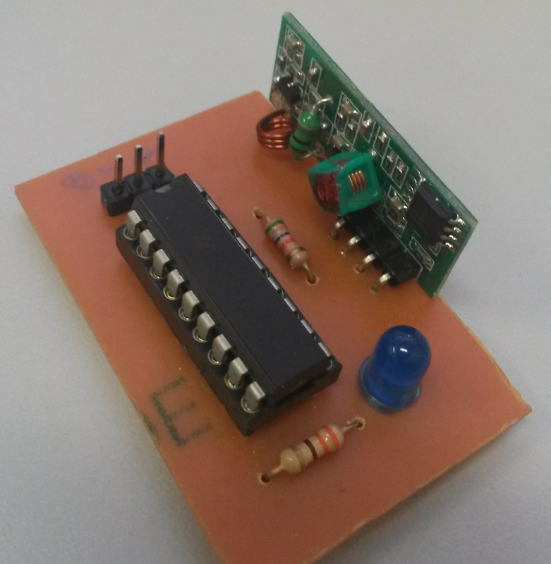
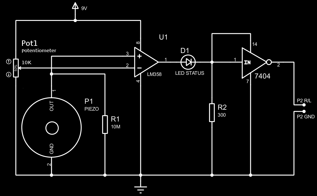
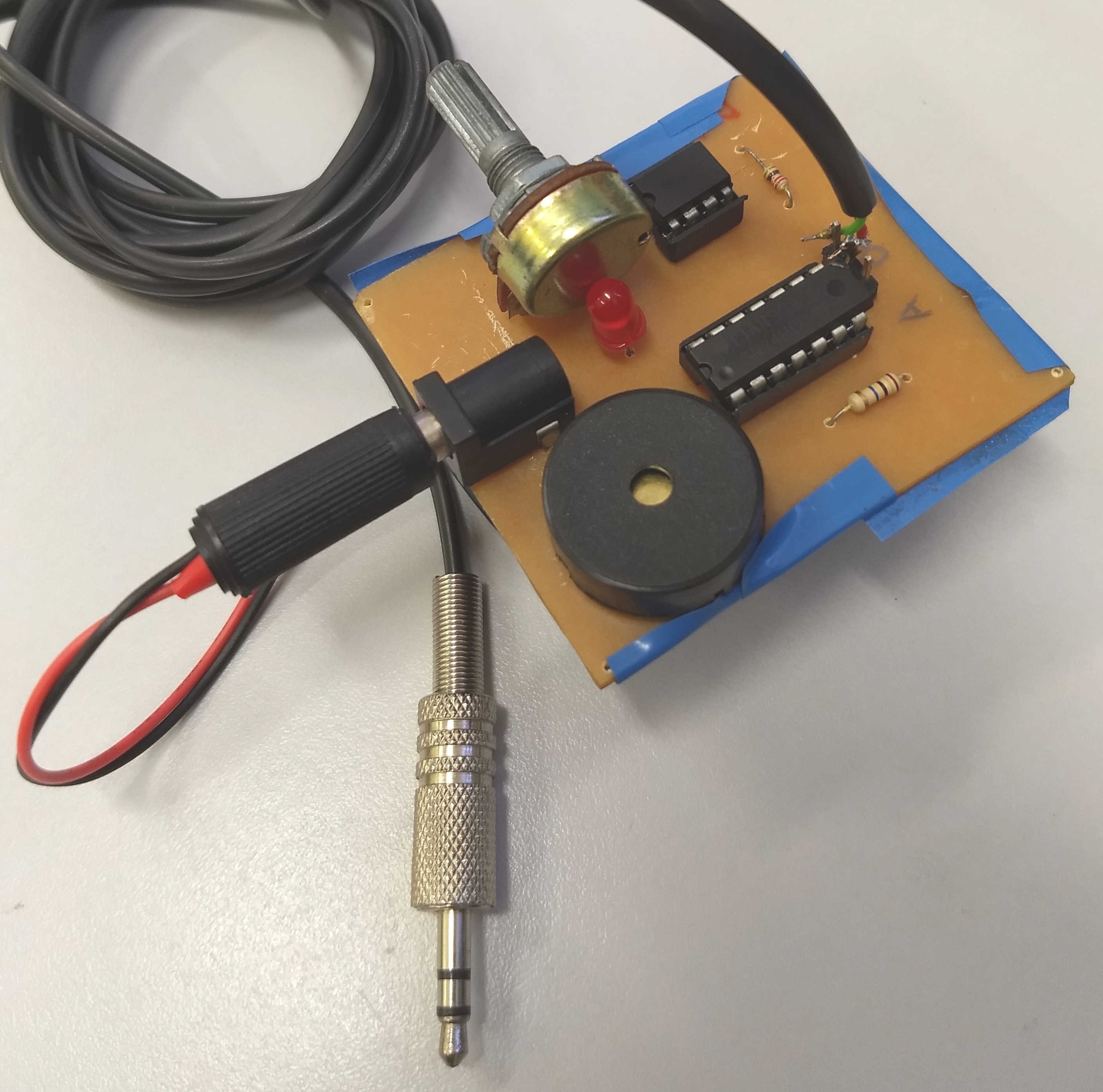
Hence, this work aims to present a solution to reduce the digital exclusion experienced by people with disabilities who are often unable to use electronic devices, due to the limitation of resources that adapt them to their needs. The overall goal of the project is to build two switches with two different forms of interaction: mouth-puffing and proximity. The output of puff-based switch is the P2 Jack audio interface, while the proximity-based, wireless one is designed to be used with microcontrollers or single-board embedded computers that provide several input pins. A schematic of the operation of the proposed devices is shown below.
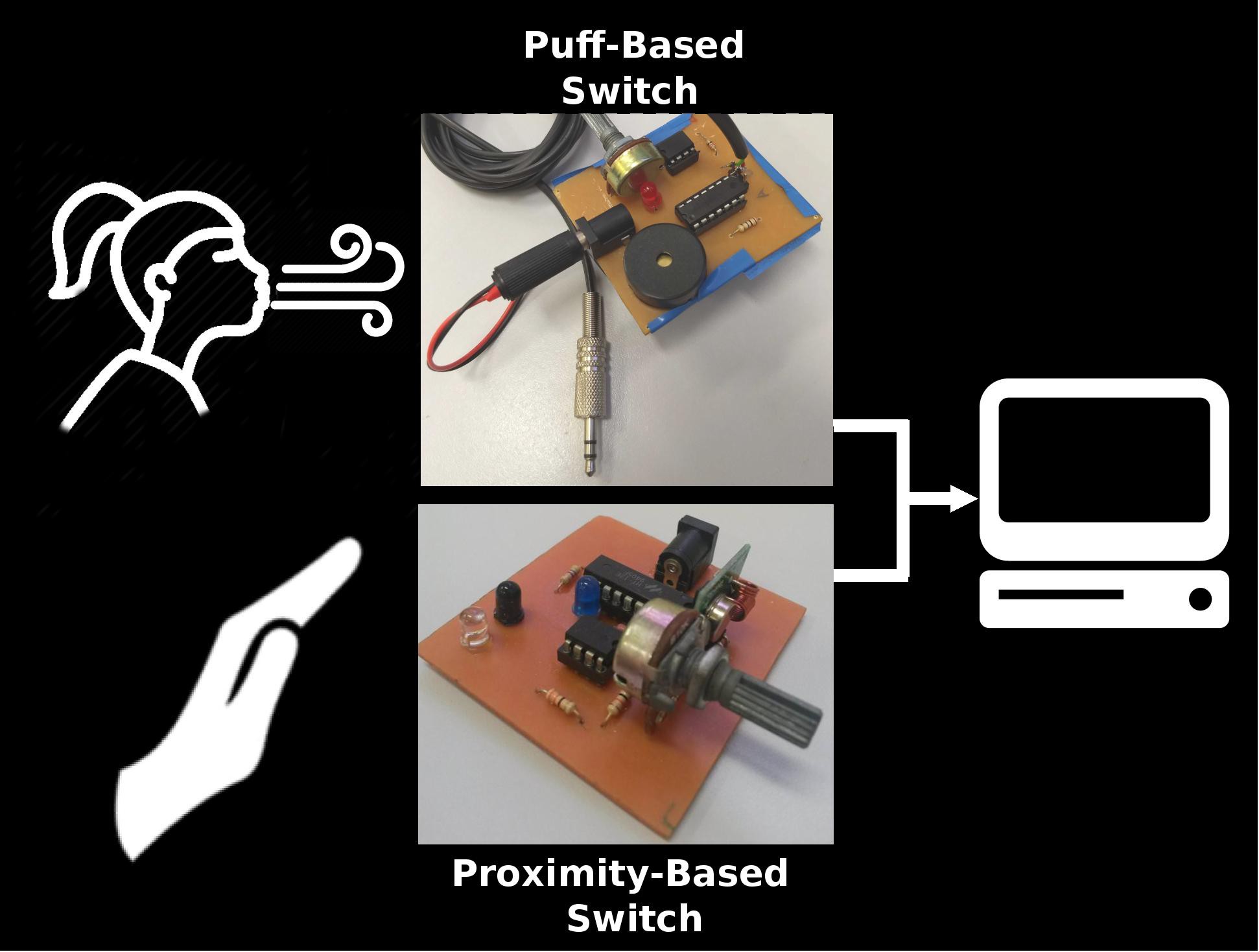
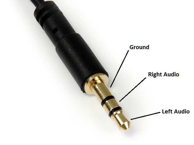
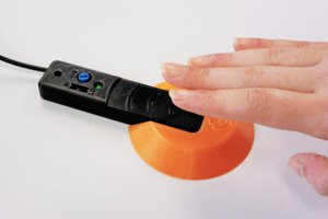
The proximity-based switch has already been successfully used on a system that controls a TV set via head gestures. The puff-based device, on the other hand, has been developed to act as the left click of the mouse. In order to the P2 Jack-based interface to be directly recognized by a computer operating system (without the need for a customized mouse with a jack input on its side), a software drive had to be developed to record audio data from the Jack input, analyse that data and convert it to click events. As far as we know, none of the switches whose output is the audio interface can control the click events of the mouse when connected directly to the computer. A demonstration of puff-based switch is shown bellow.
All tools used in this project are under license GNU General Public License v3.0.

 Makers Making Change
 Supplyframe DesignLab
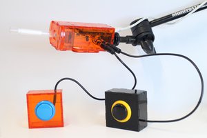
 benjaminaigner
 Roger Curry