 mauswerkz
Put the finishing touches on the layout and silk screen for my inverter control board. This board is the first I've designed using Altium. There were a few things I noticed while laying it out where the behavior of the net-naming didn't work as I expected (a power net that didn't propogate across sheets even though every other power net did, very confusing). Hopefully I didn't miss anything and there are no nasty surprises when it arrives. If all goes well, this should let me get to the real meat of the project: programming. Any other hardware I have to design for it after this should just be simple CAN interfaces and maybe a few light-duty drivers for relays or contactors.
The board is being made by Seeed and should hopefully arrive by the end of next week. Hackaday is giving away "stickvices" this week, which if I won one, would be perfect timing for board assembly. There are more than a handful of 0603 resistors to be placed, along with a few to be put on the other side. Something to hold the board off the bench while I hot-air solder (so the parts on the other side don't get disturbed) would be handy. I've been eyeing the panavises lately, especially at maker faire, but just can't justify spending the minimum of $100 on one, not to mention the suction cup wouldn't work on my bench.
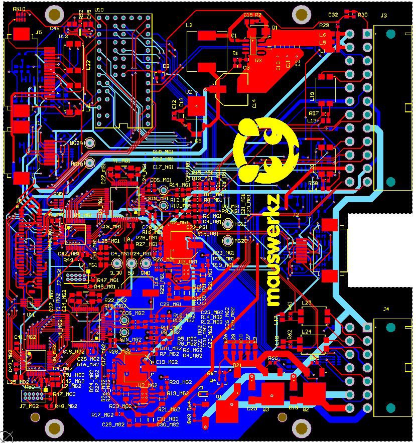
Anyway, here's a picture of the final board layout with the layers in the correct order and silk screen visible:
Discussions
Become a Hackaday.io Member
Create an account to leave a comment. Already have an account? Log In.