 Les Hall
My approach in developing these drones will be incremental. At first they will be simple sensors only. Then I will add communication of sensor readings, possibly through high brightness LEDs or through AM radio transmission. Then simple transport mechanisms will be added including tires on geared DC motors and later flight methods including lighter than air craft with drone style propulsion and actual quadcopter designs.
So the idea is to grow in complexity as time develops, starting with the simplest of basics and working up from there. It will be some weeks before I can solder again due to living space restrictions (oxygen tanks nearby!) so I will have plenty of time for planning of basic circuits and designs.
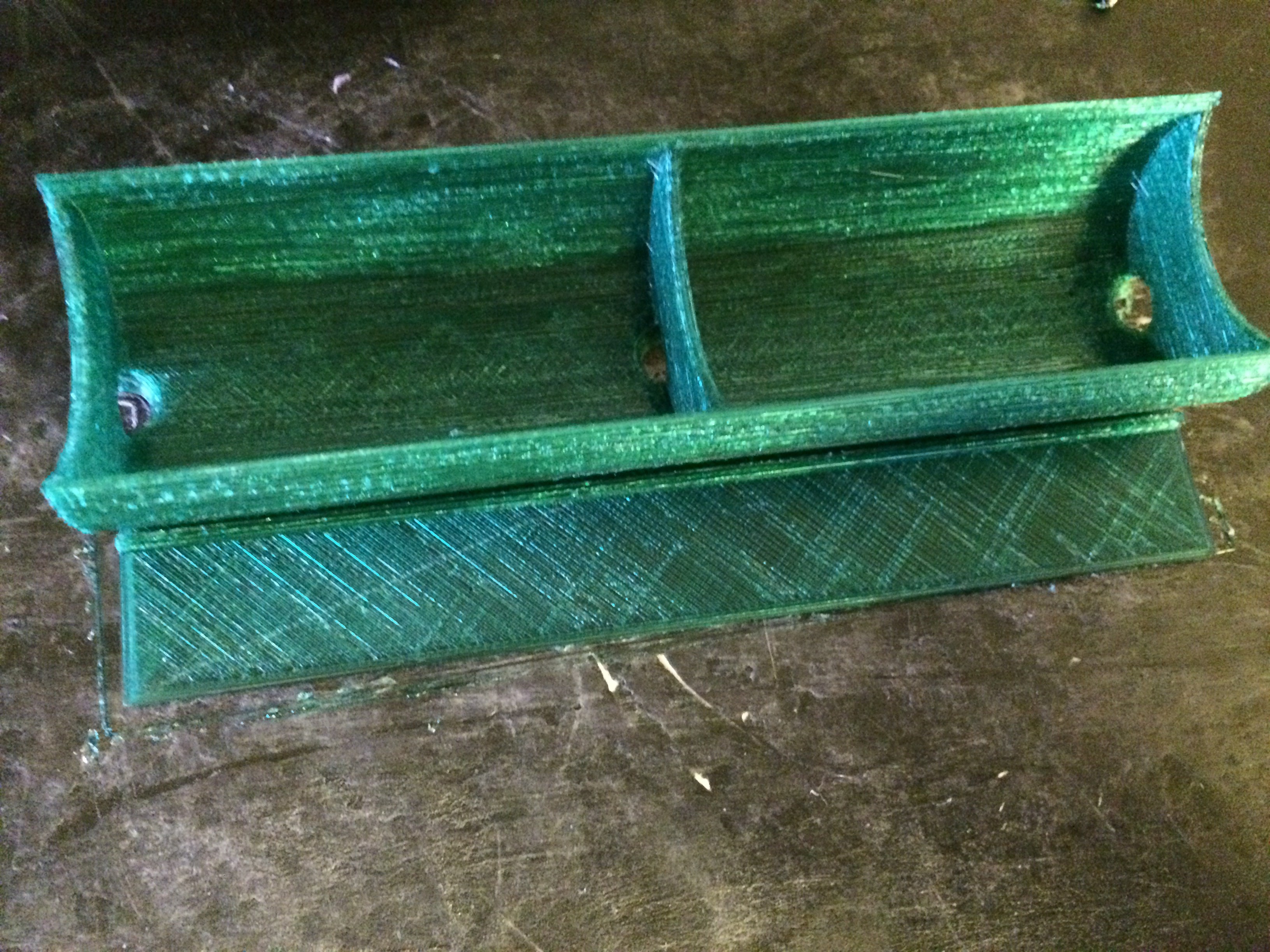
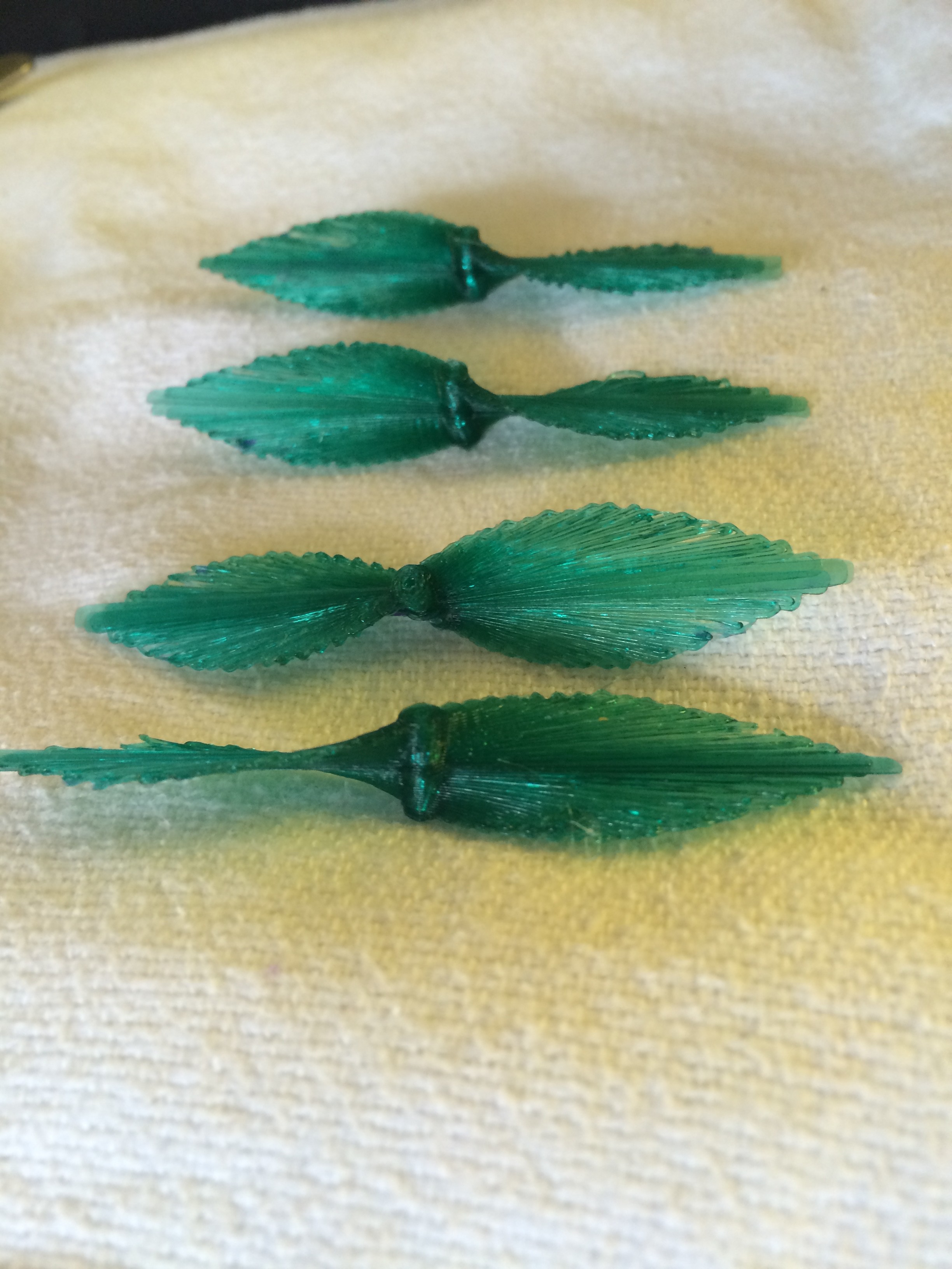 Side view of four props (glued together in pairs)
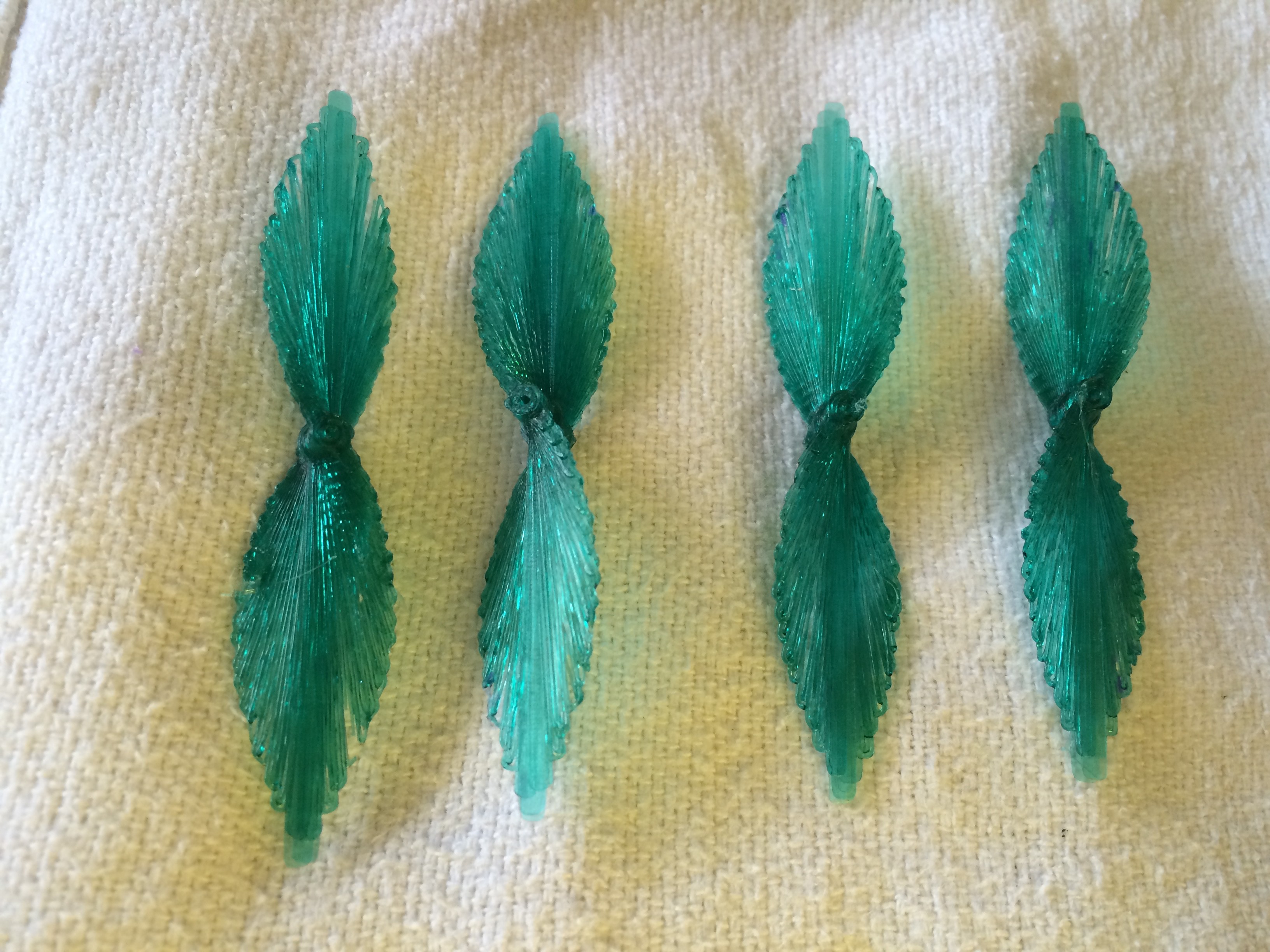
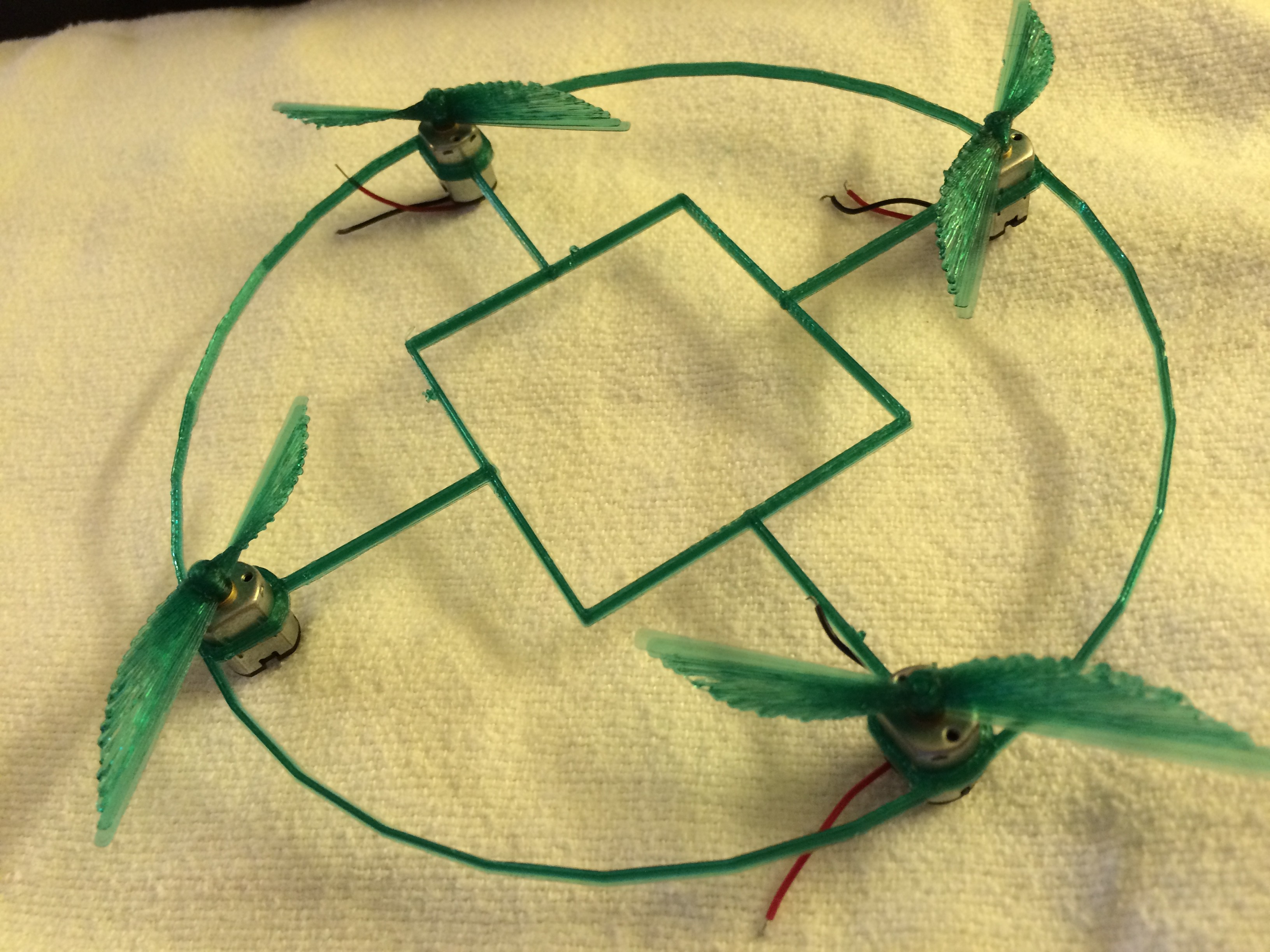
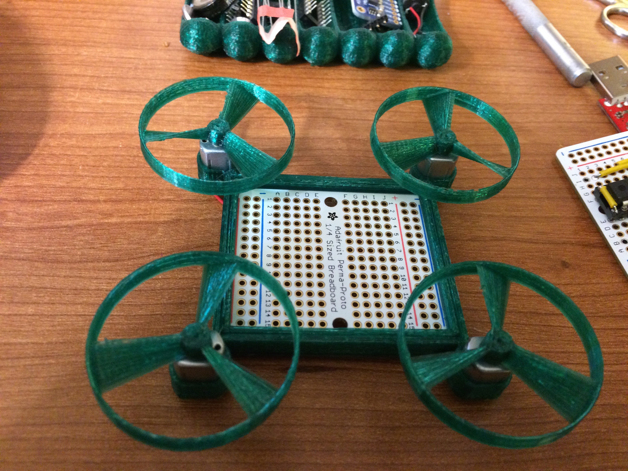
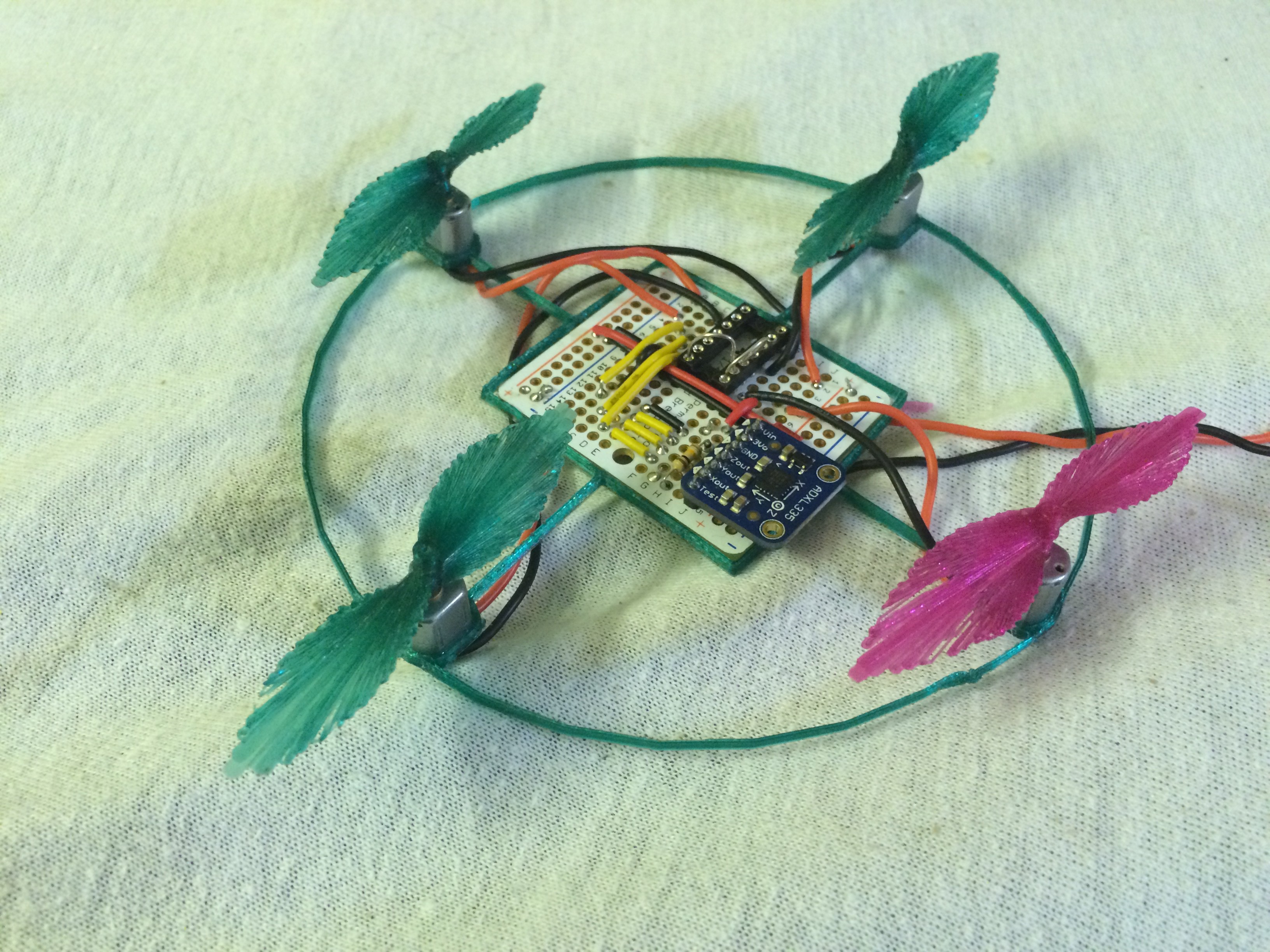
 Here you can see how a propeller can be a wheel and a wheel can be a propeller, plus probably work in water if the box is waterproofed and shaped appropriately. Of course such a craft will operate poorly in any of its three domains so it's value is in it's diverse utility. For certain situations and environments it will be well suited.
 Chris Low
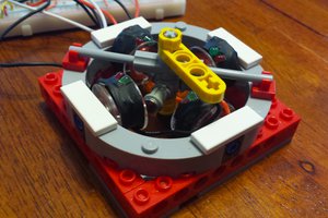
 Adam Smallcomb
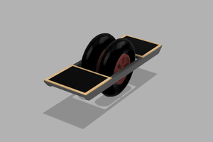
 Ilyas Akhmetzyanov