 Peter Walsh
TL;DR
A few passive components and an Arduino can measure the resonant frequency of a transducer in an automated fashion. This will come in handy when tuning the horn.
The circuit schematic is at the bottom of this post, and the program will be available on GitHub presently. Feel free to skip the gory details.
NB: As an experiment I am posting the circuit design in the style of an academic exercise in great gory detail, and I'm looking for feedback on presentation and style. Please help me out. If you think this is tedious and wasteful and too simplistic or something let me know and I'll adjust the style in future logs.
Measuring resonant frequency, the easier way
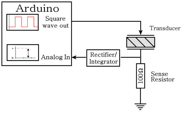
If you don't have a sweep frequency generator and/or a scope and frequency counter you can use an Arduino to measure the transducer resonant frequency. We'll need to do the measurement several times to tune the horn, so it makes sense to have a way to do this with as little effort as possible.
The block diagram circuit looks like this:
But before we hook everything up, it's a good idea to see if this is likely to work.
Design question 1: Can the Arduino source enough current?
According to the Atmel 328P datasheet (table 28.1: Absolute Maximum Ratings) the maximum DC current per I/O pin is 40 mA.
Assuming a worst case scenario when the transducer shows zero impedance, a 5V output will push 50 mA through the 100Ω resistor, and that's too much for the micro to handle.
However, the high-level output of the micro is less than 5 volts. According to the datasheet (Table 28-1. Common DC characteristics), the minimum high-level output is 4.2 volts with no "typical" or "max" values specified. Actually measuring the Arduino shows the output as 4.2 volts, so the measurement circuit will draw only 42mA .
And since a square wave is only high for 50% of the time the effective current is cut in half, so the DC current is actually 21 mA.
This is well within the rated 40 mA, so it looks like the Arduino can supply the necessary current.
Design question 2: Can the Arduino generate a fast enough frequency?
The fastest clock prescaler in the Arduino is 1-to-1 with the CPU speed, which is also the crystal speed, which is 16 MHz.
The resonant frequency of the transducer is nominally 28±1 kHz, so supposing we want to sweep between 24 and 32 kHz, the number of ticks per squarewave cycle is:
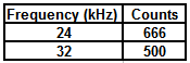
This seems reasonable. We can set timer 1 to one of these values or anything in between, set the OCR1A output to "toggle on counter reset", and the system will automatically generate a squarewave output.
Design question 3: Does the Arduino have enough frequency resolution?
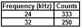
Looking at the fastest frequency (250 counts, 32 kHz), we note that the next lower frequency will be 251 counts which generates 31.872 Hz, for a difference of 127.5.
Looking at the slowest frequency (333 counts, 24024 Hz) the next higher frequency will be 332 counts which generates 24096 Hz for a difference of 72 Hz.
So we can expect the Arduino to test and measure frequencies in steps of about 100 Hz.
This isn't great resolution, but it's comparable to what you can get using an analog signal generator and a steady hand.
There's a way to get much better resolution by doing extra processing in the micro, but I'll leave that for a later post. For now this should suit our needs.
Designing the rectifier/integrator
The transducer will turn the square wave into a sine wave which goes both above and below the ground plane. We need to block the negative half and convert from AC to DC before connecting to the analog input.
(Any input of the Arduino will be damaged by a negative voltage, and the AtoD only measures DC.)
So, something like this:
Design question 4: What values of R and C should be used?
Now we need to choose values for R and C.
Looking at the frequency/count table above, a full frequency sweep will test 250 through 333 counts inclusive, or 84 tests total.
For each test, if we generate the frequency for 0.1 seconds and then measure the AtoD, a full frequency sweep will take about 9 seconds, which seems reasonable.
So we need the integrator to settle down to its final voltage within 0.1 seconds, which means that the time constant has to be short relative to that value. Perhaps 1/10 of that, so T = RC = 0.01 seconds.
So reasonable values might be 0.1 uF for C and 100K for R.
Design question 5: Will ripple be a problem?
Converting AC to DC leads to voltage ripple in the output waveform. The capacitor will charge in response to an AC pulse, then discharge when the pulse goes away. The end result is a slightly varying DC voltage, and the AtoD will see different values at different times. We need to see if this will be a problem.
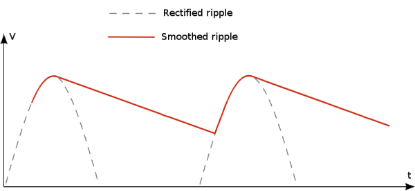
We can estimate the ripple by thinking of the capacitor discharging through the resistor after the voltage passes the AC peak.
Starting with "Ohms Law" for capacitors:
We can rearrange this as:
(T, being time, should be lower case here, but I can't seem to convince the HAD Latex editor to do that. Please bear with it.)
The dt term is the time between pulses, which is 1/frequency. The worst case in our frequency sweep is 24 kHz, for which the pulses arrive in 42 uS intervals (longest time between pulses, resulting in the longest decay time).
The current term "I" is the current taken away from the capacitor by the resistor, which is V (at the peak) divided by R. Substituting, we get:
We noted previously that the maximum voltage is about 4.2 volts, minus the voltage drop of the diode (0.7 volts), so the worst cast voltage peak should be about 3.5 volts.
And we supposed previously that our time constant T = RC is about 0.01 seconds, so plugging everything in we get:
Since our peak voltage is 3.5 volts, that's a ripple voltage of 1 part in 238, or about 0.5%.
The Arduino AtoD input has 10 bits of precision, and so can measure as little as 1 part in 1024. The ripple voltage should be within the lowest 2 bits of the AtoD converter.
In reality the peak voltage will be less than 3.5 volts since the transducer will never have zero impedance, and this will make the ripple voltage a bit less than calculated.
Also, we approximated the ripple by assuming that the capacitor would discharge over the full time period. In reality, the capacitor only discharges to the point where the next pulse arrives, as shown here:
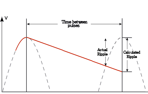
We also played fast and loose with the differential in the equation above by breaking it into two pieces. In reality the capacitor discharges exponentially (not linearly, as shown), but this works out in our favor because beyond the first moment of discharge the capacitor discharges more slowly than calculated.
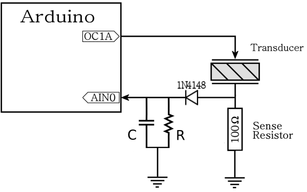
The final circuit:
So the final circuit looks something like this:
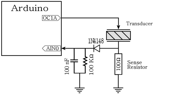
I checked the output using a scope, and found not a hint of ripple. More importantly, the output doesn't look like it will damage the Arduino.
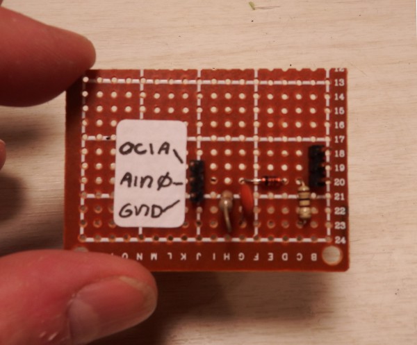
A little bit of perfboard, and here's the final result:
Discussions
Become a Hackaday.io Member
Create an account to leave a comment. Already have an account? Log In.
why do you give the signal back to the arduino in this, what is the purpose of that i could not understand. You have already powered xducer with the frequency required and we just can calibrate it and find the frequency using the resistor, isn't that it.
Are you sure? yes | no
does that mean you have not write code for arduino to detect and lock resonance frequency?
Are you sure? yes | no
I have the code, but it's not an Arduino sketch. It's a bare-metal program.
The newer system works much better, but requires more hardware. I'm integrating it with an LCD display and some extra hardware for voltage protection.
Are you sure? yes | no
dear peter...thanks for reply...
can you send me the code ? my email is aymanok@gmail.com
thanks
Are you sure? yes | no
I bundled the code up into ResonanceFinder.zip file and put it up on GitHub here:
https://github.com/Sonicators/UltrasonicSystem
Are you sure? yes | no
I'll be happy to send you the original code, but read the rest of this first.
Firstly, the code isn't a sketch: it runs on the bare processor. In order to use the code, you'd have to have the ability to burn code in place of the Arduino bootloader, then replace/reburn the Arduino bootloader if you decide to use the board as an Arduino in the future.
More importantly, I've since decided that using the Arduino to generate/sweep frequencies doesn't work. The frequency resolution that you can get is about 100Hz at 28KHz, and your resolution will be about double that.
The manufacturer will guarantee that the resonant frequency is within some error of the rated frequency, typically +/- 200 hz, so you need to be able to distinguish frequencies at a more fine-grained level to determine the actual resonant frequency.
I'm now using an AD9833 sine generator to generate the frequencies. This has a lot of frequency resolution, and it's "set and forget" from the micro so it's easy to program. It uses a rock-standard SPI interface. You can get a breakout board with all the extra passives on eBay for not much money:
http://www.ebay.com/itm/Programmable-Microprocessors-AD9833-Sine-Square-Wave-DDS-Signal-Generator-Module-/231520649582?hash=item35e7b4c16e
I put the AD9833 output through an op-amp voltage follower to boost the power, and use the same inverter/integrator section of the above circuit.
This works very well, it gives me the ability to sweep frequencies with very fins resolution, and the extra power makes the a perfect trace of the output impedance - even better than Lindsay's version.
It's been on my task list to make a combined frequency sweep system with Arduino and display, with alligator clips to attach to any transducer and measure the resonant frequency - I just haven't gotten around to it.
I've got working code for the AD9833 board, which also isn't a sketch, but you should be able to adapt it to the Arduino software pretty easily. My driver for the AD9833 board is here:
https://www.dropbox.com/s/qvx8ju6zlmq48o7/AD9833.zip?dl=0
As to your question, I believe the resonant frequency will be unchanged.
A piezo element can be modeled as a series LRC system, where the C is the capacitance of the connecting electrodes, L is the mass of the resonating system, and R is losses due to friction. I *believe* that putting the system in water will increase the R value without changing L and C, so that the system will resonate at the same frequency, but have more losses. Your plot will have a smaller dip at resonance, reflecting more loss of energy and a smaller "Q" value.
...but do the experiment and let me know what the results are.
For a fluid filled container, would water work? Water has a huge shear modulus, and it's easy to drive out dissolved gases by boiling (you need a degassed liquid in any event). It's also cheap, and won't undergo weird chemical reactions under high pressure from the pinging.
Just asking - you've probably already looked into this and I'm curious of what the research says.
Are you sure? yes | no
Peter
This looks really useful. Can you send me the Arduino code? I have just joined Github but still cant find the code. Must be doing something wrong.
I am making an underwater pinger which uses a cylindrical piezo tube from STEMinc. Its going to be fitted in an oil filled pressure housing so I am thinking that I need to do my measurements with the piezo in the oil filled bath and not in air. Do you agree? Its fq is stated as 43khz in air but it will be different in oil.
Many thanks in anticipation
Barry Norman
Are you sure? yes | no