 Peter Walsh
Quick Summary
1) Arduinos can only generate 28kHz signals to a resolution of 120 Hz. That's not enough for this project.
2) Using digital pots to control analog systems is totally feasible.
3) A simple control algorithm can get a resolution of ±2Hz.
3) An algorithm based on control theory might be even more accurate.
Arduino generated signals have poor resolution
This project uses PWM signals in the ultrasonic range, around 28kHz. Since the transducer gets warm in operation, the resonant frequency changes which causes variations in the delivered power. For a consistent power output (and to prevent burning out the transducer) the system needs to adapt to these changes and make appropriate adjustments.
An Arduino can generate a repeating signal by connecting the CPU clock to an internal counter: every N CPU clocks the output changes state, making a square wave on the selected pin.
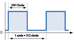
For Arduinos running at 16 MHz, this won't have enough frequency resolution. Taking 32kHz as the upper bound the output-compare counts 512 system clocks per cycle, and you have to change the output pin twice in each cycle so the output compare needs to count to 256 for each pin change.
A table of counts and generated frequencies shows that this method doesn't have a lot of frequency resolution. Going from one count to the next changes the output by about 120 Hz, or 1%.
That's not a lot of resolution.
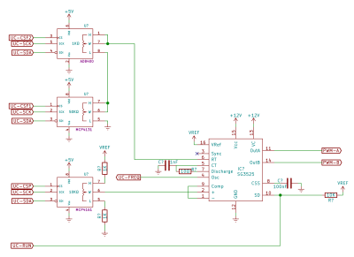
So for the transducer project I decided to try controlling an analog signal generator using digital pots. The UC3525 is essentially an RC oscillator with a pulse width generator, both of which can be controlled by a fixed resistance.
A digital pot typically has 128 or 256 positions, and is "set and forget" from the microcontroller. This frees the micro for other tasks such as power monitoring and user input, and also simplifies the control software.
Having 256 steps is still not enough resolution for the frequency range needed (I want to sweep from 20kHz to 32 kHz), but the range can be extended using two pots in series: a coarse setting of 50kΩ in series with a 1KΩ fine setting gives effectively 3Hz resolution on the frequency setting.
Results
I was surprised at how well this actually works.
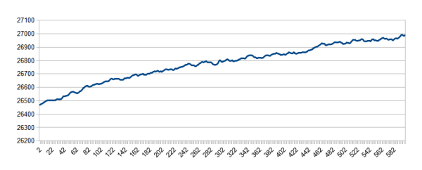
The first image below shows the free-running (ie - no feedback) system for the first 10 minutes at startup. The frequency drifts higher over time, presumably due to components warming up. After warm-up the system shows slight variations over time, as seen in the second image. Considering that an Arduino-generated output will have a resolution of 120 Hz, the 150Hz variation over 10 minutes seems reasonable.
 The previous images had no feedback control from the micro. With the controller measuring the output and adjusting the pots the variation in frequency becomes much less. In a 10-minute stretch of output the 1-second counts show a remarkable accuracy. The microcontroller adjusts the resistors 25 times each second, so the frequency will be high or low in any specific time slice, but the overall accuracy (total pulses per second) is quite accurate.
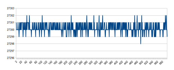
Setting the system to bump the frequency by 1 Hz shows a similar accuracy.
The feedback/control algorithm is a simple bang-bang control that increments or decrements the fine control pot as the measured frequency is below or above the setpoint.
A proper PID control system would probably have even more accuracy.
So in summary, microprocessor control of analog systems using digital potentiometers seems to work. It's a viable technique that could be used to control many types of analog systems.
Discussions
Become a Hackaday.io Member
Create an account to leave a comment. Already have an account? Log In.