 Peter Walsh
We're coming to the run-up for the Hackaday Prize judging, and Mike Szczys mentioned offhand (at Artisan's Asylum, last week) that they're planning a blowout final interim prize before the Aug 17th deadline.
This seems like a good time to do a project roadmap and retrospective. I wanted to get my regrets out of the way before the contest begins in earnest :-)
Project Future Roadmap
I'll be exploring the Haber process using various means (mostly ultrasonic) for the next couple of years. I was planning this before the contest announcement, and I'm in it for the long haul. What this means is that The Hackaday Prize isn't my primary motivation. One way or another I'll be doing this long after the contest has ended; though, probably not with weekly updates in "diary" style.
So the roadmap for the project during the contest period, and after is:
- Take the project as far as possible in the Hackaday Prize contest. The prize awards are mid November, so that's an outer limit on this phase. (Estimate: End of August to mid November, depending on how far the project gets.)
- Take some time off to decompress and cleanse my mental palate. (Estimate: 1 month.)
- Do some project house cleaning: adding README's, verifying file headers, rearranging directories... general prep work for first release. (Estimate: two weeks.)
- The ultrasonic system will go up on GitHub as a public repository. Anyone can download the schematics, source code, hardware layouts and everything else.
- The chemistry/experimental side will go somewhere else, possibly Hackaday.io.
- The GitHub account will be open to anyone who wants to join the project and otherwise help with development.
- The chemistry part will be open to anyone who wants to discuss and make suggestions on what experiments to try. It'll also be open to collaborators (ie - join the Hackaday.io side as a contributer).
Things that should be different
I've made a lot of progress in figuring out how to do things for the project, but there are some rough edges. Individual rough edges are not a problem, but they combine to make the final project a bit difficult. I've been forging ahead due to contest requirements, but I really need to revisit some design decisions and rework some of the earlier phases.
Horn Tuning Circuit
Don't use the Arduino to generate frequency
As mentioned in a previous build log, an Arduino has about 100Hz of frequency resolution at 28KHz.
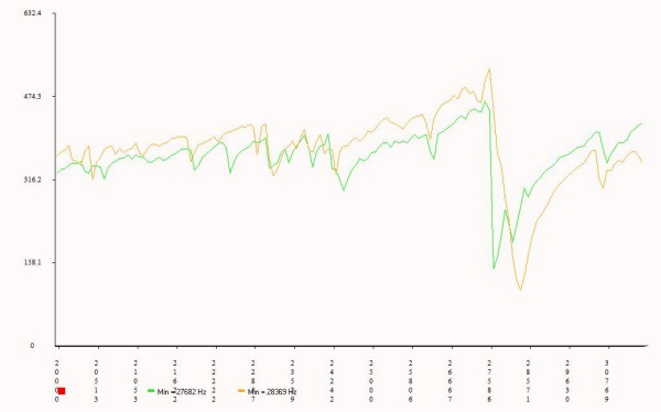
This seemed reasonable at the time, but in practice I'm finding it difficult to tune the horns using that resolution. The transducer has a very thin resonance window, 25Hz or so, and you can't judge how close the horn comes to that frequency.
The image on the right shows the bare transducer response (orange) and horn response (green) during the tuning process. The 28KHz peaks "mostly" overlap, but it would be nice to see a more fine-grained resolution here.
Using a faster processor could work, but isn't the best solution.
Don't use square waves
Square waves are easy to generate, and it *seemed* like a good idea because you can turn them into sine waves by filtering. In reality, this bring a host of problems to the circuitry, and filtering never completely works. Especially at 400V and 100 watts.
New design
I've been working out a better design using AD9850 to generate pure sin waves with sub Hz resolution. It's a little more expensive, but a demo board including resonator is about $8 on eBay, which is cheaper than the bare chip from DigiKey. It's "set and forget" from the uController, reduces the board chip count, and greatly simplifies the software. The pure sin waves should be easier to filter than square waves.
I think the generated sine can be split into positive-going and negative-going parts, then fed into a class-D amplifier to run the power driver board. The class-D PWM should generate a pure sin wave out of the transformer, while keeping the FETs either completely on or completely off.
I'll be working on the new design during the contest period.
Horn Tuning
It's difficult to turn down horns on a lathe due to their length. A standard rest (follow or steady) will badly gouge the surface, so you need a "wheeled" rest, which is typically too small for a horn.
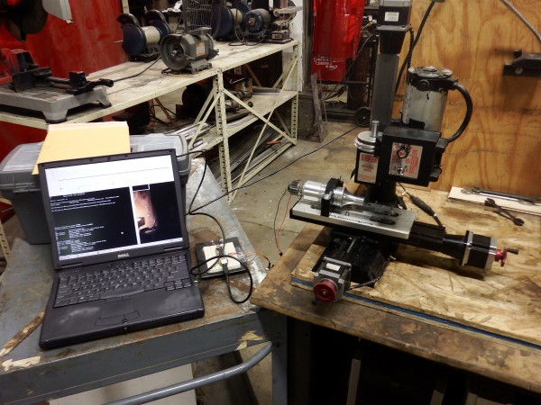
A metal cutting table saw (or radial arm saw) blade will reliably cut a horn blank, and a small CNC (one that can cut aluminum) can carve down the profile. Then the CNC can progressively face the ends while measuring the resonant frequency. This is *much* easier than chucking and unchucking the horn during the tuning process.
CNC horn cutting and tuning works well, and small CNC's are probably more hobbyist accessible anyway.
Don't connect the transducer to anything while adjusting
CNC'ing the horn with the transducer attached generates massive voltage spikes into the measurement circuitry. Simply *attaching* the horn to the transducer while connected is enough to fry the measurement components. Sxperimentally determined, hindsight is 20-20.
Isolate the transducer except while measuring
The new power supply can make the AD9850 pure sin wave available, so you won't need a separate board for tuning.
Also, a relay can keep the transducer disconnected except during measurements. Otherwise the relay will short a low-value resistor across the transducer to prevent voltage spikes.
Better mounting while tuning
The transducer mount for the tuning process could be better. The system needs to hold the transducer and horn steady enough for the CNC to face the end, but lightly enough so that the tuning process still works.
Right now I'm loosening the bracket before each measurements. If I could eliminate this step, I could completely automate the tuning process.
Step horns don't work at all
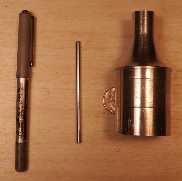
As part of the project I'm reproducing Lindsay Robert Wilson's step horn - and not having any luck. My parabolic horn tuned up exactly as expected, but the step horns... nothing. The system behaves as if the step horns aren't connected at all, and I haven't the first clue why this is.
I've got 3 step horns of various configurations, one shown here, and none of them seem to do anything.
I'm completely at a loss as to why this is.
Anyone have experience with ultrasonic horns and can give me a hint?
Discussions
Become a Hackaday.io Member
Create an account to leave a comment. Already have an account? Log In.