 Peter Walsh
TL;DR
.) Looking to hire someone to solve a n electronics problem
.) New driver board is partially working
.) Version 2 of some of the project pieces
.) GitHub groups open for contributors
Looking to hire a consultant
I'm having a lot of trouble designing the power-drive section of the new board, and would happily pay $100/hr for someone to just slam dunk it for me.
This *should* be straightforward: it's a common ham radio circuit, and there's lots of people with switched-mode power experience who should be able to get a prototype working in an evening.
I need to boost a 1v p-p sine wave to 12 volts at 10 amps and I'm done - the rest of the board is working, the microcontroller works, the PC software works, the horns are tuned, and the transducers sing.
I only need that 1 piece of the puzzle to complete the project. A complete description is here.
Know someone who can help?
(NB: I am not looking for advice. Please don't contact me just to say what I should do, I'm looking to hire someone to do the work.)
New board design is partially working
The new board design uses an AT9850 sine-wave generator for sub-hz resolution. This works perfectly.
This has solved all of the problems with transducer and horn tuning. I can now cut horns close to a transducer frequency, and see very clearly how well tuned it is and how to trim it for resonance. Horns can be tuned using a mill, a lathe, or a CNC mill (quite possibly a Shapeoko would work), so lots of hackers should be able to build one of these if they want.
I'm trying to integrate the tuning circuit into the power driver board as a separate output, so I don't have a board image or schematic to show. But it works.
The new circuit will have a relay (a real one, not solid state) to disconnect the transducer during the tuning process, so that cutting vibrations won't generate back EMF spikes that kill the tuning circuit.
Power drive doesn't work, need new solution
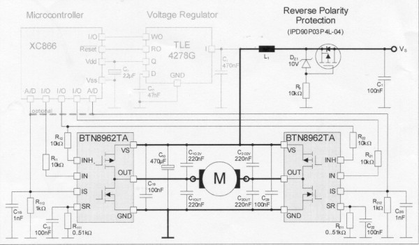
I had originally planned to convert the 1v p-p sine wave into PWM using a class-D amplifier (that part works) and switch a pair of half-bridge motor drivers in H-bridge configuration with the transformer primary in place of the motor.
This should have worked.
The BTN chips are made for inductive loads, they can handle the frequencies, they've got plenty of power (40 amps, of which I only need 10), they're made for PWM control, they have logic-level inputs, and they've got embedded current sensors. What's not to like?
The problem is they don't work.
The logic-level inputs don't behave like binary inputs - sometimes a high level will turn the device on, and sometimes it won't. No amount of fiddling or driver chips or adjusting input resistors affected the behavior. And yes, the datasheet specifically states that the inputs are logic level, with reasonable logic-level mins and maxes that *should* be triggered by a 74HC14 driver chip.
Also the outputs seem to be deceptively analog - the output levels sometimes go up to the 12-volt rail, and sometimes they don't. This is particularly evident when using a PWM signal, since some pulses are 12-volt high while others are not. It's not a speed issue: sometimes the relatively slow pulses peak at 10 volts, sometimes they peak at 12.
The manufacturer has a 24/7 help line which wasted a lot of time - I tried chat, phone, and E-mail, and each time the operator advised me to call back using a different channel. I'm still waiting on a response from the "open a ticket" answer.
Several frustrating days later and I'm giving up. These chips aren't ready for mainstream.
Project, Version 2
(Oh, I am *so* jonesing to try making ammonia with this system, but I need to finish the driver circuit to stay in the contest. I'm focused on that all the time. Even in my sleep.)
I've revised some of the project hardware.
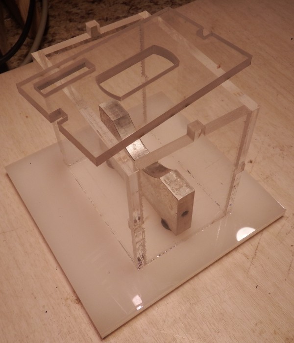
The new reaction chamber has alignment notches. If you look closely you can see glued notches in the edges of the main body, and the unglued notches in the lid keeps it from sliding around during experiments.
It's now much easier to assemble and glue.
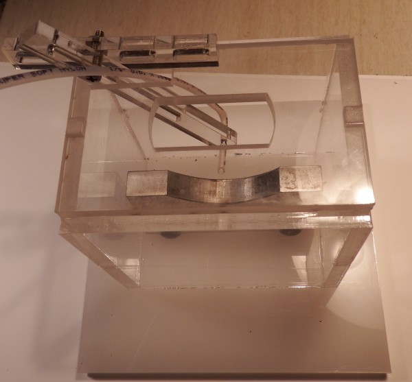
A new tube holder allows me to adjust the position of the end of the tube in 3 dimensions without getting my fingers wet.
This is a little wobbly - could probably use a version 3.
The transducer flats are bigger than a common box-end wrench, and steel wrenches have a tendency to mar the aluminum horn and steel transducer, so I cut out an aluminum wrench using a CNC. Version 1 and version 2 in the image here.
Github groups
Schematics and software are up on GitHub.
The hardware will go up soon, I just wasn't able to get to it in time for the contest deadline. Hardware consists of transducer mounting hardware, the reaction chamber, wrenches... mostly DXF files for the laser cutter and some gcode.
I also created two GitHub groups for people who want to help out: "Sonicators" for people who want to help develop the ultrasonic system, and "AmineGroup" for people who want to contribute experiments and projects using the system.
Contact me on .io or through GitHub if you want to be added to either group.
NOTE: You do NOT need to be a group member to access the files. The repositories are open source, they can be downloaded and used by anyone. The groups are for people who want to help. Group members have write-access to the repositories.
Discussions
Become a Hackaday.io Member
Create an account to leave a comment. Already have an account? Log In.