 M. Bindhammer
Just two examples: If your breath has an acetone-like odor, it's a warning sign for diabetes and if your breath has an ammonia-like odor, it's a warning sign for chronic kidney failure.
Target gases of the FIGARO TGS 2620 sensor are amongst other substances: ammonia, propionic acid, acetic acid, acetone, benzene and ethanol, which makes this gas sensor with a heater current of only 42 mA and a standard TO-5 package suitable for simple breathing gas analysis.
Fig. 1

The basic measuring circuit for the TGS 2620 is shown below:
Fig. 2
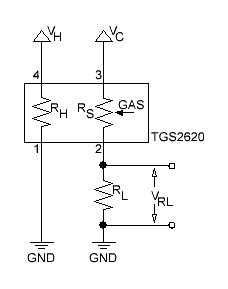
The formula to determine RS is given by:
The value of RL should be determined to make the output voltage half of VC at the most critical value in the sensor application, because then the output voltage of the voltage divider is most sensitive to the gas concentration.
The relationship between sensor resistance and the concentration of deoxidizing gas can be expressed by the following equation over a certain range of gas concentration:
where
RS = Sensor element resistance
A = Constant for this particular gar sensor
C = Gas concentration
α = Slope of the RS curve on a log/log plot.
The equation for the minimum value of the load resistance RL to limit power to the sensor element resistance RS is given by:
VC = 5 V and PMAX = 15 mW = 0.015 V·A, thus
A little bit more advanced gas sensing circuit is shown in next figure:
Fig. 3
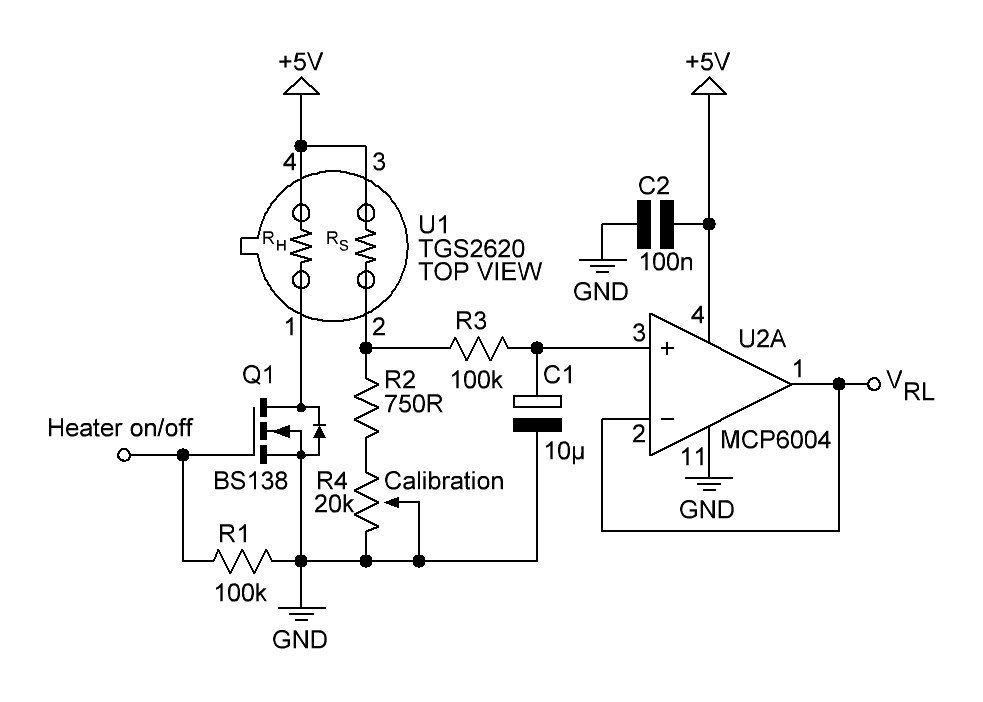
Q1 turns the heating element of the gas sensor on or off. R2 and R4 acting as a variable load resistor. The R3/C1 circuit provides a low-pas filter with a cut-off frequency of
The op-amp U2A is connected to an unity buffer amplifier circuit.
Breathing gas analysis and respiration rate system overview:
Fig. 4

If the patient breathes out, breathing gas enters the system and must overcome the small resistance of the check valve. The resulting pressure increase will be recognized by the pressure sensor. The breathing gas flows then to the gas sensor, where it will be analyzed. When the patient breathes in, the check valve closes and no false air intake can take place.
Pressure sensor will be a MPXV5004GC6U from Freescale with a pressure range of 0-3.92 kPa (0-400 mm H₂O).
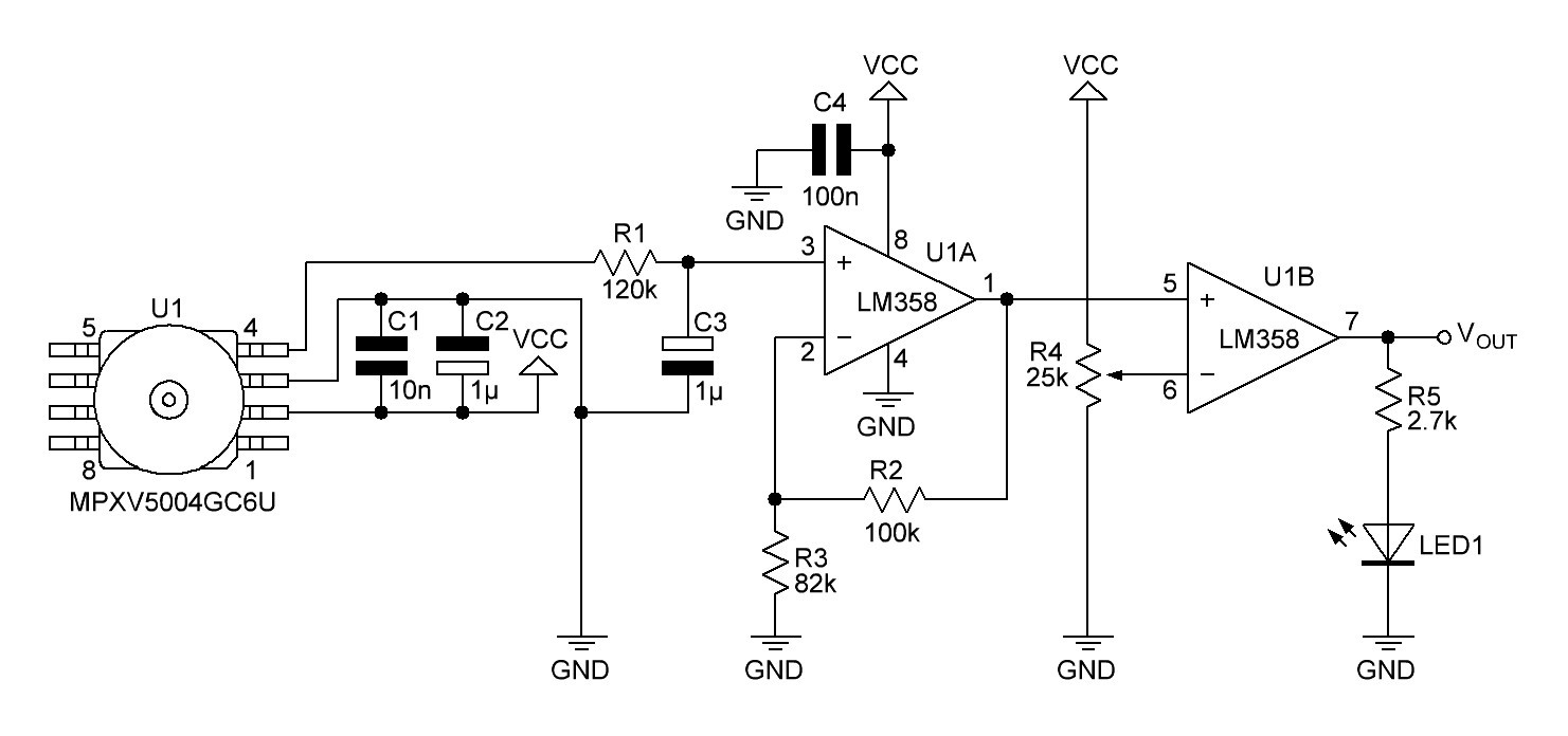
The gauge pressure is quite small when breathing out, so the output voltage of the pressure sensor must be amplified. This is done by a non-inverting amplifier:
Fig. 5

C5 and C6 are recommended decoupling capacitors. R9/C7 are connected to a low-pass RC filter with a cut-off frequency of
The output voltage of the non-inverting amplifier (and input voltage VIN of the non inverted Schmitt trigger) is given by
Assuming a single power supply of the op-amp and a rail-to-rail output, high threshold voltage VH, low threshold voltage VL and hysteresis H are computed as follows:
After experimenting with several setups I decided to use a non inverting comparator and a low pass filter with a cut-off frequency of 1.6 Hz instead of the Schmitt trigger.
References:
Technical Information on Usage of TGS Sensors for Toxic and Explosive Gas Leak Detectors
Noise Considerations for Integrated Pressure SensorsNon-Inverting Schmitt Trigger Calculator
LM358 datasheet
Discussions
Become a Hackaday.io Member
Create an account to leave a comment. Already have an account? Log In.