 Andrew Mayhall
Alright! So in my last log I tore into the Pacific Hydrostar pump and got to the juicy insides.
First, I decided to go ahead and cut off the armature from the main shaft and then grind in a flat to create a D shaft. No turning back now!
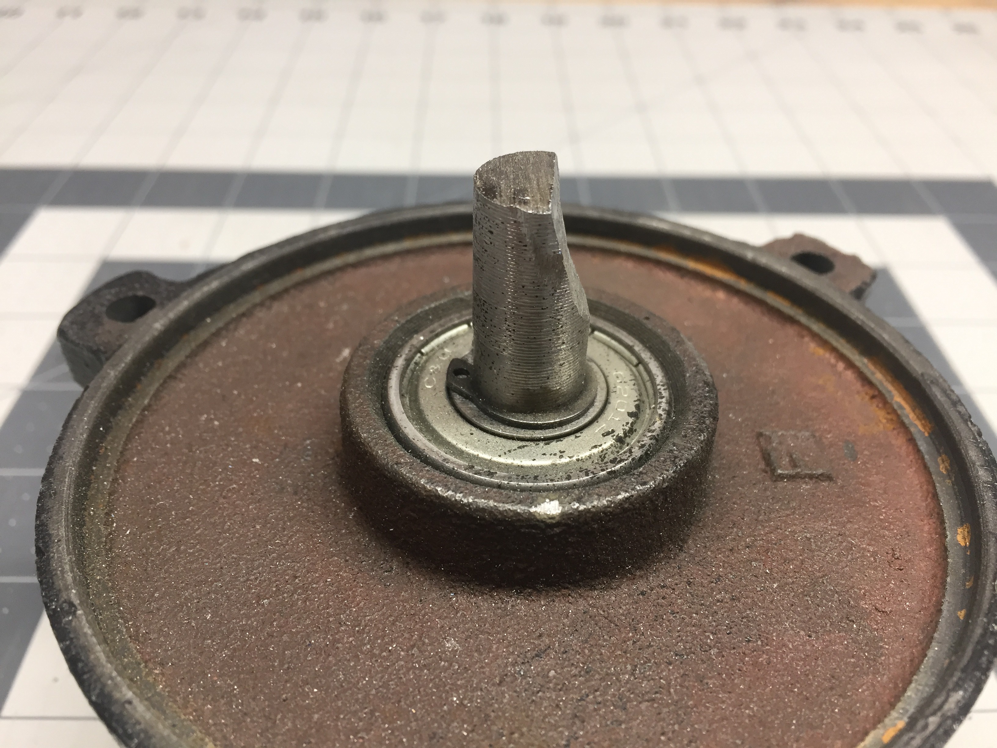
Instead of going for just a flat D shaft I decided to angle the grinding so to provide a good positive stop where the coupler would be mating to the shaft.
Next I shifted focus to creating an assembly within solidworks and beginning the process of working out the geometry of the coupler and come up with some sort of housing for the BLDC motor.
Once the pump was completely broken down capturing the necessary measurements was pretty straight forward.
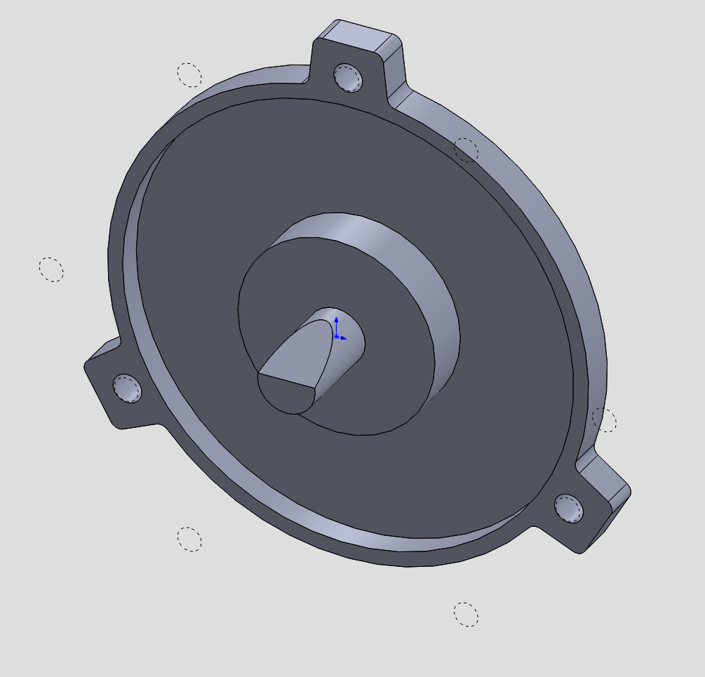
Using just the essential information I proceeded to build a rudimentary mock up of the mounting flange for the pump casing.
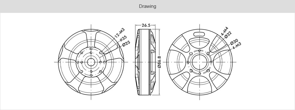
Next, I needed to mock up the BLDC. Thankfully, T-Motor provided a technical drawing so this was very straightforward.
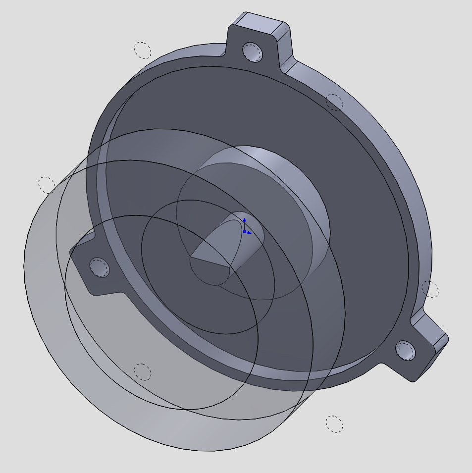
Here I have a rough approximation of where I would like the flange and motor to be positioned.
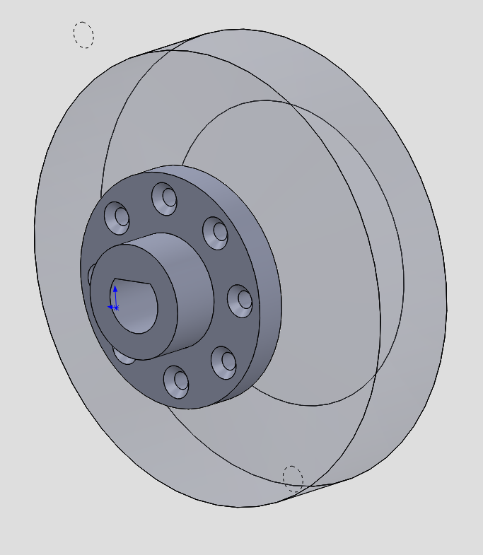
Now I think this is a good time to consider various options for coupling the shaft to the motor. T-Motor provides a ring of 8 M3 tapped holes around a 35mm circle. They also provide a precision(ish) indexed hole of 13mm in the center of the motor.
I think the straight forward approach would be to make an adapter out of SLS nylon that features a locating pin of 12.95mm in the rear and a mounting flange for the 8 M3 fasteners. A collar would extend from that flange and encase the modified D shaft.
Overall, its a simple design that should work just fine. For my application I am not going to need the full output pressure of this pump and therefore I'm not really concerned about the stresses this coupler will be under. And hey, if it breaks I can just print another!
Before calling this part done I think it wold be important to address the cooling issue of this motor. Given that this particular motor is designed for multi rotor drones with big ass fan blades attached cooling isn't something that should be an after thought here.
There are a number of ways I can go about cooling this motor, from an eternal DC fan, to a simple paddle style centrifugal blower attached to the motor.
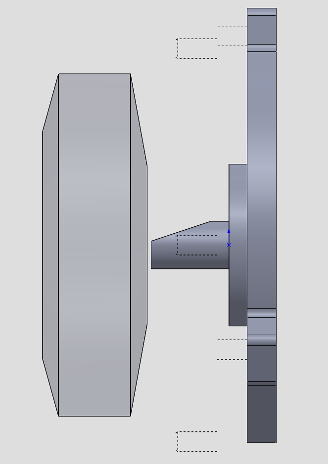
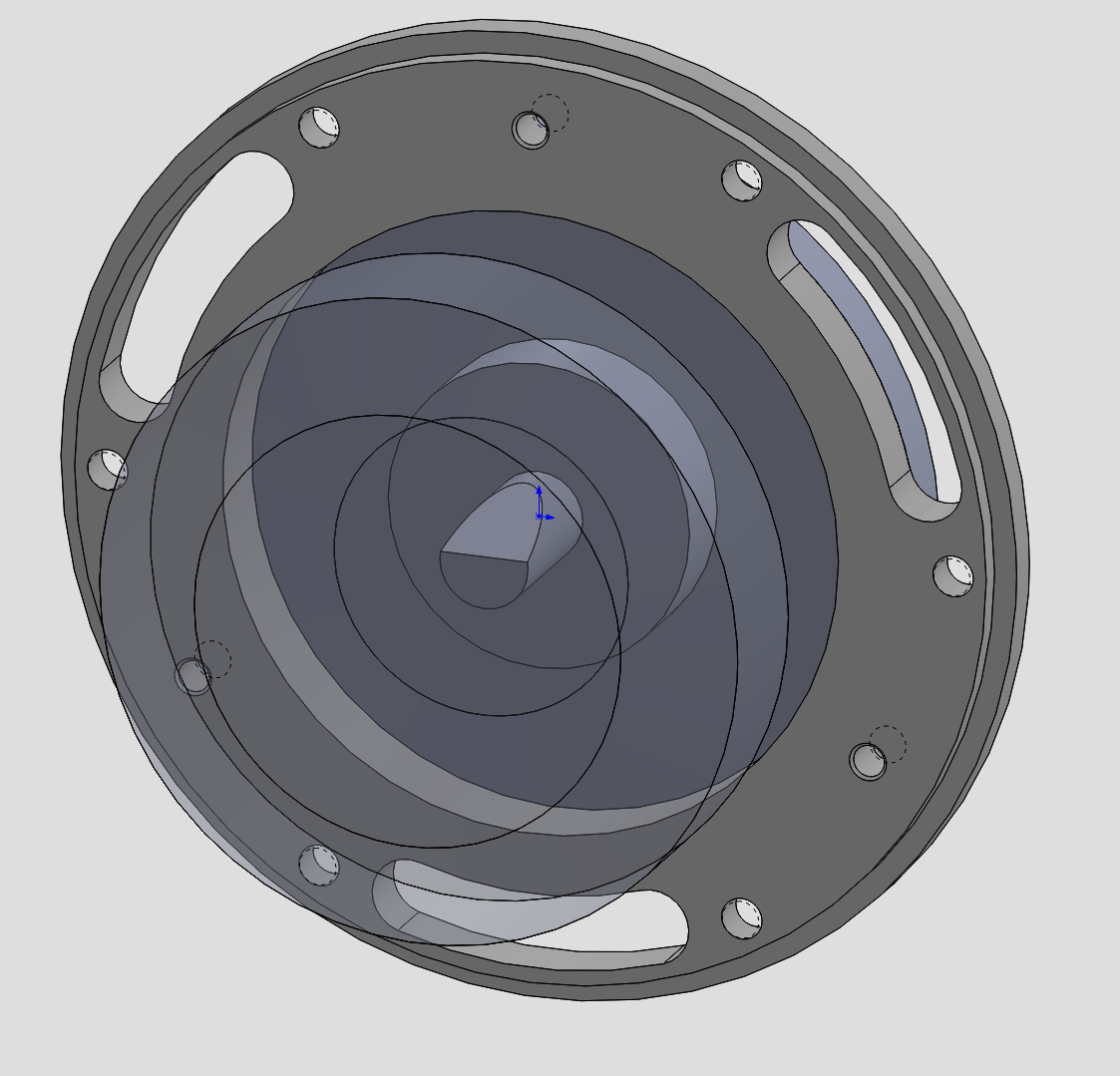
In this case, I saw an opportunity to build in a simple axial fan directly onto the coupler. This way, as the the motor would run cooling would be forced though the open stator of the motor providing cooling.

The design is pretty straight forward and an angle of 30 degrees should be adequate enough to move air though the motor. I'm not going for high efficiency here or an optimized design just something that will work and keep the motor from burning up!
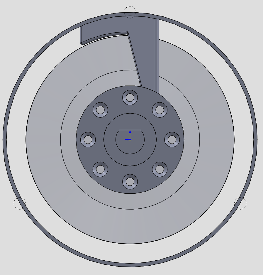
One of the considerations I had to weigh was a trade-off of size. Specifically related to making the cooling fins the same diameter as the motor or extending them slightly to increase airflow.
On one hand, I don't anticipate needing the full power of this pump and the small cooling provided by simple fins should be enough to keep everything with boundary conditions. This would mean that I could keep the motor housing roughly the same diameter as the original motor and have a straight forward housing design.
On the other hand, adding extra cooling capacity would be beneficial if I ever wanted to increase the pumps output or potentially overdrive the motor slightly for whatever reason. Increasing the fin length would mean that I would have to add an adapter to the main pump casing flange to accommodate a larger diameter housing.
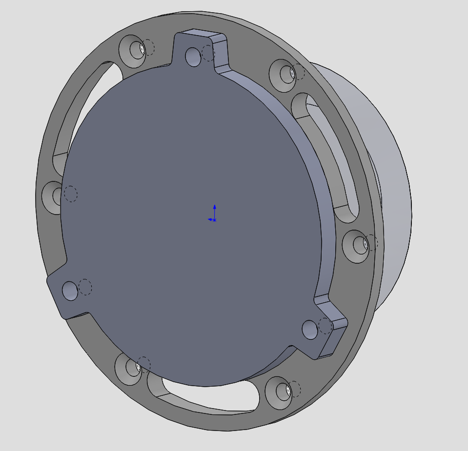
Ultimately I decided that the use of an adapter flange wasn't a big deal and opted for the extra cooling. (Boy does it work!)
Since opting for the larger fan, the housing would need to be bigger too. This housing is designed to serve four purposes. One, provide a fixed mounting position for the BLDC motor. Two, couple the stator of the motor to the pump casing mounting flange. Three, provide ducting for the cooling fan ensuring airflow across the motor stator. Four, provide a stable base to affix the entire pump assembly.
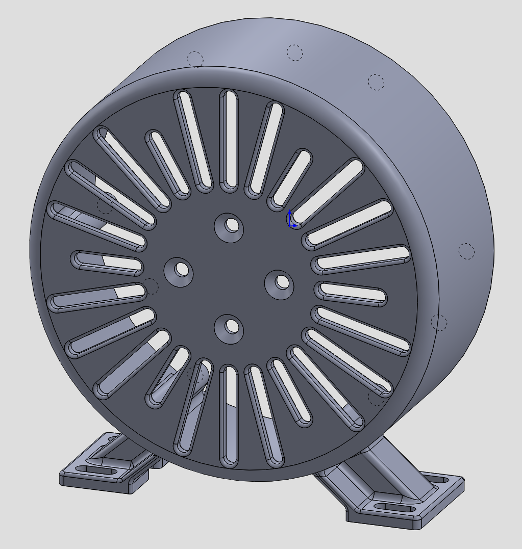
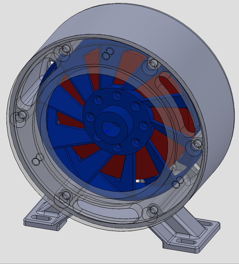
While being a relatively simple design this housing is the single part that makes the whole pump work. Its also the last part that is needed to make the Franken pump operational so now comes the fun part of actually building this monstrosity!
In the next project log I will go over the assembly and give everyone a peak at the operation!
Thanks again for checking out this project. Please stay tuned for the next update!
Discussions
Become a Hackaday.io Member
Create an account to leave a comment. Already have an account? Log In.