Close
0%
0%

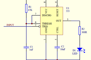
LED Time of Flight Ranger

Use some fancy timers to measure the speed of light

Similar projects worth following
An attempt at making a basic LIDAR. I worked on this back in 2015. Circuit creates a high current pulse to drive an IR LED, and is built around two TI TDC7200 timers to measure the time until a return pulse is received. The first timer measures the leading edge of the pulse, and the second timer measures to the trailing edge of the pulse. This provides two measurements to help cancel out thresholding effects when the pulse edge is not sharp. A high speed comparator is used to threshold against a DAC output. An 8 bit processor is used to orchestrate.
I ended up giving up on it for two reasons: I accidentally supplied 5v to the circuit, and the sensitive timers have a max of 3.6v and they got hot. I also realized that the parts count was getting huge to get this to work, and that the range would not be that great. Posting here in case it gets anyone else thinking.

Ranger Code v1.0.zip

Preliminary IO with the timers

x-zip-compressed - 121.67 kB - 02/04/2018 at 13:12

Download

brd - 66.22 kB - 02/04/2018 at 13:11

Download

sch - 191.90 kB - 02/04/2018 at 13:11

Download

ranger receiver1.0 opt.brd

Note that the part footprint for the input stage amplifier (MAX3806) is wrong in this file - see replacement board.

brd - 179.44 kB - 02/04/2018 at 13:09

Download

sch - 857.03 kB - 02/04/2018 at 13:09

Download

Enjoy this project?

Share

Discussions

Similar Projects

Does this project spark your interest?

Become a member to follow this project and never miss any updates