Close
0%
0%

MFOS Modular Synth

A Music From Outer Space modular synthesizer

Similar projects worth following
This is a transcription to KiCAD of Ray's Wilson synthesizer modules and a construction of a modular synthesizer based on his desgins

I have always been fascinated by modular synthesizers but such awesomeness comes with a exorbitant price tag.

A couple years ago I found MFOS and gave it a look, but never build any of the projects in that page.


Cue in me some years older, and a lot more bored and this project is born :D!

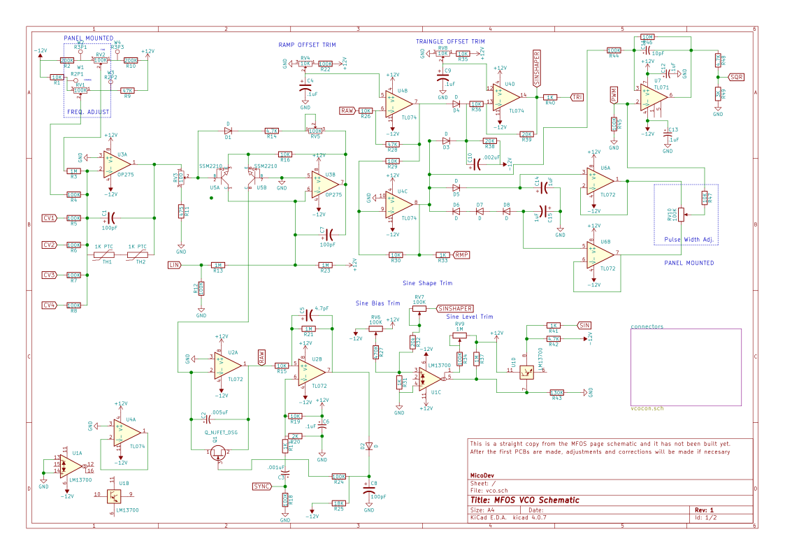
If you visit the MFOS webpage, if you haven't done already, you will find that Ray Wilson was very passionate about sharing his love of synthesizers with the world, so I am sharing all the schematics, gerbers and problems I might have during this journey with the Hackaday community, in hopes that someone else finds this useful, or even tries to build one with me.

As Ray used to say: Keep imagining, keep inventing, stay ingenious!

vcomfosmicolab.rar

gerbers for v.1 mfos vco

RAR Archive - 323.20 kB - 02/27/2018 at 16:01

Download

  • VCO: Initial Considerations and Front Panel

    Micosilent02/07/2018 at 11:45 0 comments

    The heart of an analog synthesizer its the Voltage Controlled Oscillator ( or VCO ), so logically the first module I am going to start working with is the VCO.


    Front Panel

    The synth cabinet is going to be based on the eurorack form factor, so the size of the front panel must comply with the "standard".

    A typical synth enclosure is 6 HP units high, accommodating two rows of modules, each 3 high, and 84 HP units wide, so if we want a rack enclosure with 4 VCOs they should be 10 units wide, so they only take up half of the top row.

    Following this guidelines, the aluminum front panel is 128.5mm high by 50.50mm width and the PCB in order to fit in normal fabhouse board size limits will be 100x50mm with a few mm of margin if we need the space.


    A SVG of the front panel design has been made, so it can later be transfered to a piece of aluminium with the toner transfer method

    I will probably invert this design, so its a black panel with white text.

    The PCB will be mounted to the front panel with the potentiometers and audio jacks, so no holes for mounting are needed


    Schematic Transcription

    The original VCO schematic are two pictures on the MFOS website, so I've made them again in KiCAD, in order to be able to layout a new board.

    The original design specifies  a temperature compensator, witch after some research turns out to be synth lingo for a thermistor, a PTC thermistor to be more exact. The one used in the original design is a 2k with a very low tolerance. These have been proven difficult to find in the usual distributors, so two 1k .5% PTC thermistors in a 1206 and very close proximity to the matched transistor package will be used

    The PCB layout will be done in the following days, and after the PCB is sent to the fabhouse, the KiCAD project will be uploaded to the project page.

View project log

Enjoy this project?

Share

Discussions

stevehunt100 wrote 06/04/2018 at 09:01 point

Hi, very nice, could you share the Kidac .sch file please :)

  Are you sure? yes | no

Similar Projects

Does this project spark your interest?

Become a member to follow this project and never miss any updates