 Casual Cyborg
This week we address algorithms, code, and appearance. Or cases.
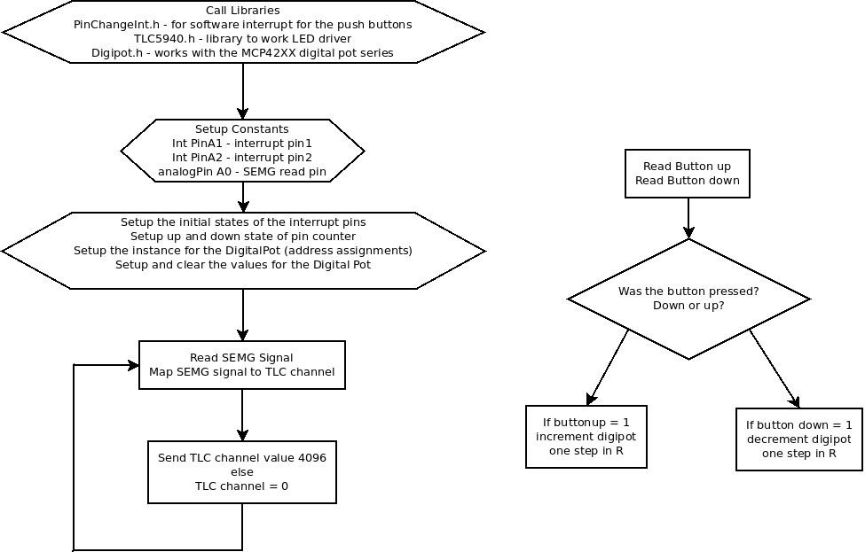
Let's start with code. For a device like this, where we're not interested in doing any kind of medical work - plus we don't want nor need to deal with the FDA - and it's just involved in controlling digital outputs for lights, artificial muscles, servos, etc, you don't need a lot of accuracy. The Arduino's 10 bit ADC is sufficient for most project needs when it comes to that. That greatly simplifies our processing. The basic functional requirement is to read in the SEMG signal, map the signal out to the PWM ports of the TLC5940NT in ascending order, and allow for software interrupts using soft IRQ's for button push instances so that when the button is pushed, the MCP42XX digital pot either lowers the resistance or increases the resistance to increase or decrease the gain so we don't oversaturate the final output signal.
The Atmega328P we're using is the low powered one, which works at 3.3V. Obviously if our signal overshoots 3.3V, we won't get a useful reading, so having the gain adjustable on the fly is necessary.
Right now, as it is, the program is a hack, due to the preliminary board being manufactured proof of concept. So, a lot of the dedicated serial channels that the Arduino uses isn't standardized across the board. Instead of the I2C port, which is the Analog 4 and 5 ports, we have it occupied by the switches for the MCP42XX, which is the SPI digital Pot. For the SPI, which typically is PWM 11, 12, and 13, we have that taken up by the TLC5940NT.
That's a real mess.
Anyway, here is the flowchart program for the circuitry.
And here's the code. Starting with the main function in the Arduino.
#include <PinChangeInt.h>
#include <DigiPot.h>
#include <Tlc5940.h>

#define Int_Pin1 A1  // assign Analog1 to be the Interrupt Pin 1, Up Pin
#define Int_Pin2 A2  // assign Analog2 to be the Interrupt Pin 2, Down Pin

#define analogPin A0  // select Pin 0 for analog input

volatile int state = LOW;
volatile int state2 = LOW;

int StateUp;  // the button up state
int StateDn;  // the button down state
int PressUpNum;  // the number of button presses for the up button
int PressDnNum;  // the number of button presses for the down button

int valueUp;  // The previous value of the Up button
int valueDn;  // The previous value of the Down button

int slider = 5;  //setup variables for the digital pot 0
int val;

DigiPot mcp4251(5, 6, 7);  // Start instance mcp4251
/* Format: DigiPot <instance>(CS, SCK, SDI) */

uint8_t latest_interrupted_pin;
uint8_t interrupt_count[2]={0};  // Setup two interrupt pins

void setup() {
  StateUp = digitalRead(Int_Pin1);  // Read in the initial state
  StateDn = digitalRead(Int_Pin2);  // of the Interrupt Pins

  PCintPort::attachInterrupt(Int_Pin1, digipot_slider, CHANGE);  // Call the Interrupt
  PCintPort::attachInterrupt(Int_Pin2, digipot_slider, CHANGE);  // Call the Interrupt

  mcp4251.clear(0);  // Clear the pot 0
  mcp4251.clear(1);  // Clear the pot 1

  Tlc.init();
  Tlc.clear();
  //Serial.begin(9600);

}
void loop() {

  muscle_semg_read();
  //Serial.println(slider);
}
void digipot_slider() {

  valueUp = digitalRead(Int_Pin1);  // read in the current state
                                 // of the button up pin
  valueDn = digitalRead(Int_Pin2);  // read in the current state

/* Start of the Decision Tree for Up and Down Buttons */

  if (valueUp != StateUp) {  // if the value changed
    if (valueUp == HIGH) {        // and if the button is on
      if (0 < slider < 10) {
      // PressUpNum++;            // Add one to the number of presses
      slider++;

      // Serial.println(PressUpNum);
      // Serial.println(slider);
      }
    }
  }
  StateUp = valueUp;        // make the buttState current

  if (valueDn != StateDn) {  // if the value changed
    if (valueDn == HIGH) {    // and the button returned (pull up)
       if (0 < slider < 10) {
         // PressDnNum++;
         slider--;
         // Serial.println(PressDnNum);
         // Serial.println(slider);
       }
    }
  }
  StateDn = valueDn;      // make the buttState current

  if (slider < 0) {
    slider = 0;
  } else if (slider > 9) {
    slider = 9;
  }

   val = map(slider, 0, 9, 0, 255);
   mcp4251.write(0, val);
}
void muscle_semg_read() {
int sensorReading = analogRead(analogPin); // read in the Analog pin data
//Tlc.clear();
for (int channels = 0; channels < 11; channels += 1) {
} // run through channels 0-9 for a total of 10 channels and clear them
int channels = map(sensorReading, 0, 1024, 0, 11);
// loop over the LED array
for (int TlcLED = 0; TlcLED < 11; TlcLED++) {
// turn the channel on
if (TlcLED < channels) {
Tlc.set(TlcLED, 3000); // set the luminosity at max value
//Tlc.update(); //send the data to the TLC5940NT
}
// turn off all pins higher than the channels level
else {
Tlc.set(TlcLED, 0);
//Tlc.update(); // sedn the data to the TLC5940NT
}
Tlc.update();
//delay(50);
}
//Tlc.update();
//Serial.println(sensorReading);
}
Cases
Here's the thing about mixing circuitry with clothing. Or at least, circuit boards, with clothing.
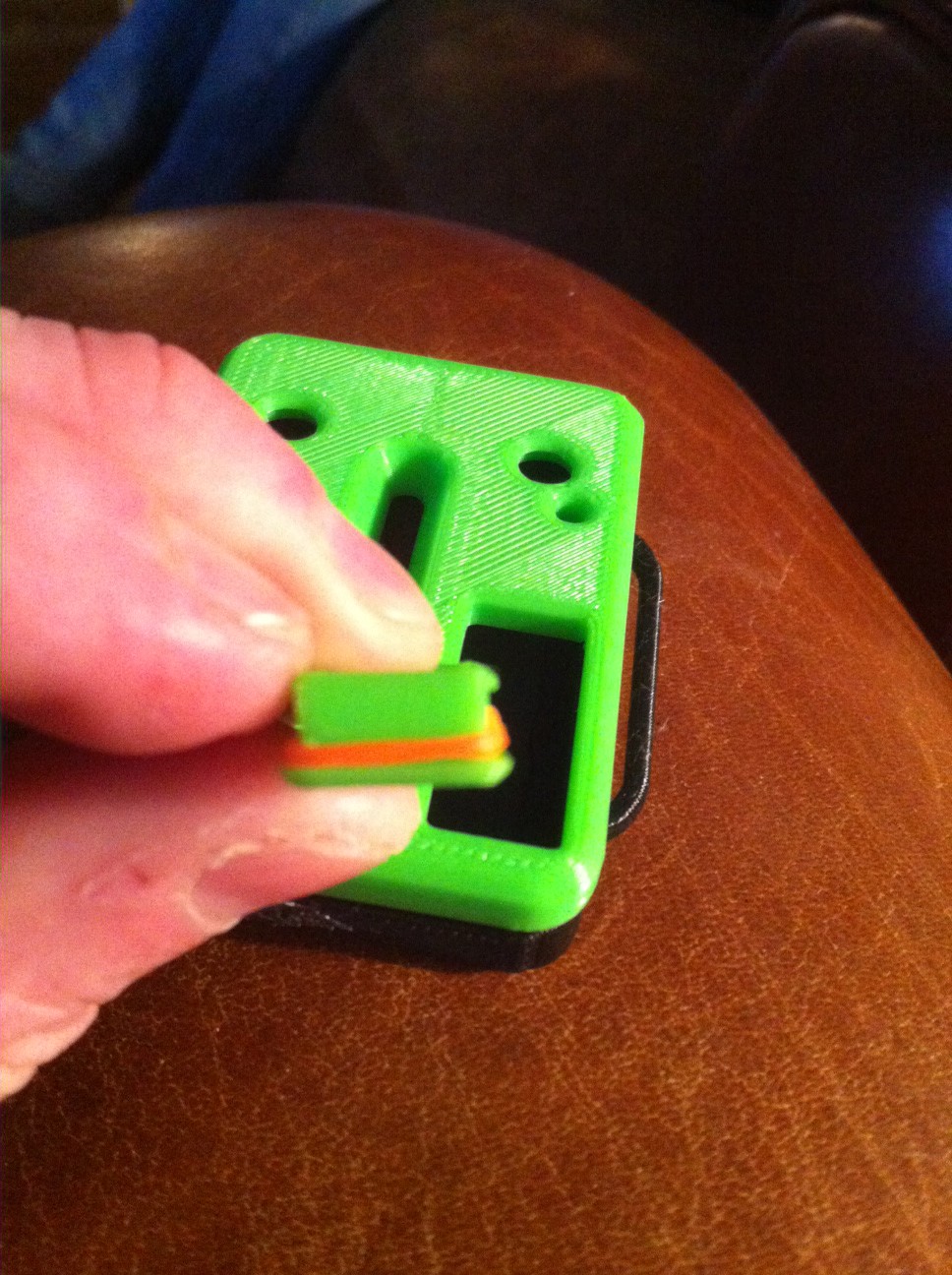
It's uncomfortable. I've gone running with all kinds of crap strapped to my body. And that $#it is just plain uncomfortable! About the only thing I can really stand using is a watch. So, while the form factor of the board is far nicer, it's still a circuit board. Which meant that I had to come up with a piece of packaging to make this somewhat presentable. What I came up with was this.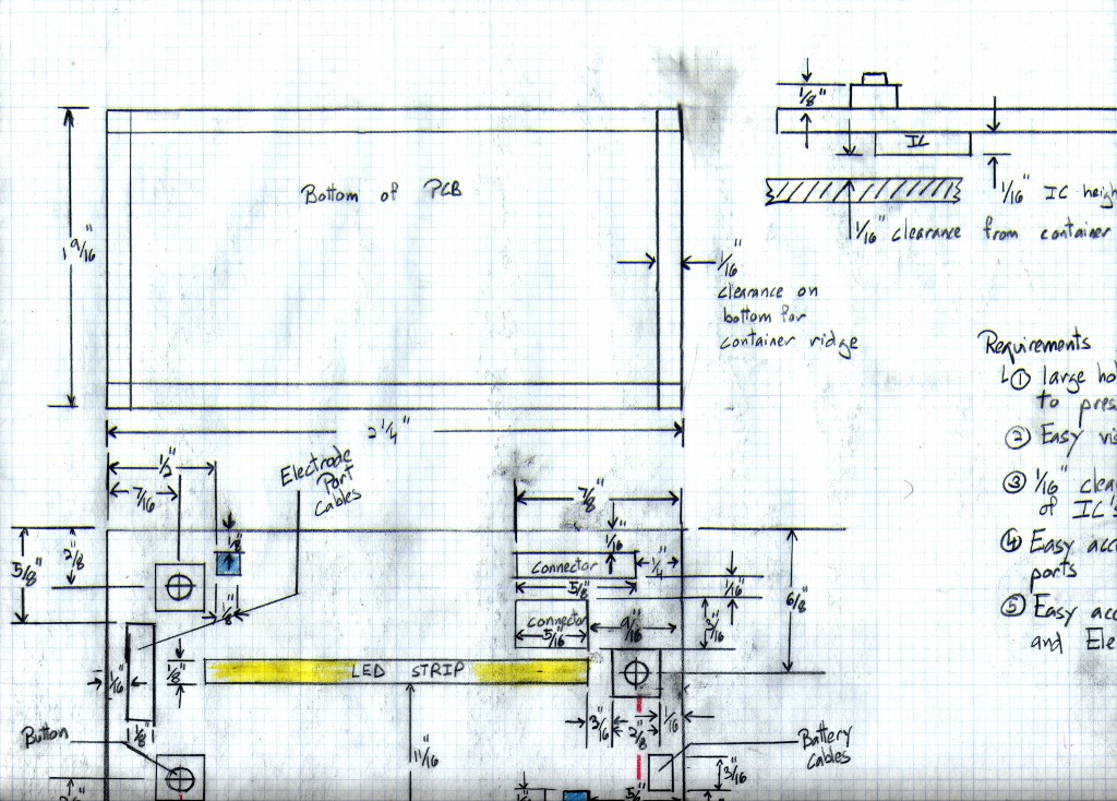
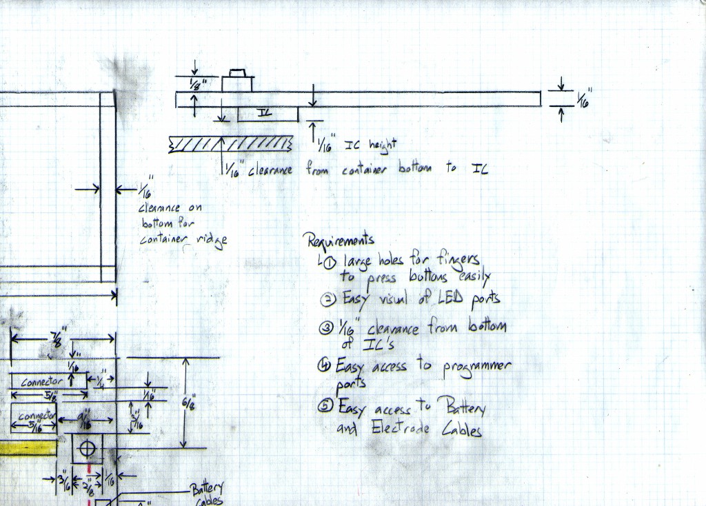
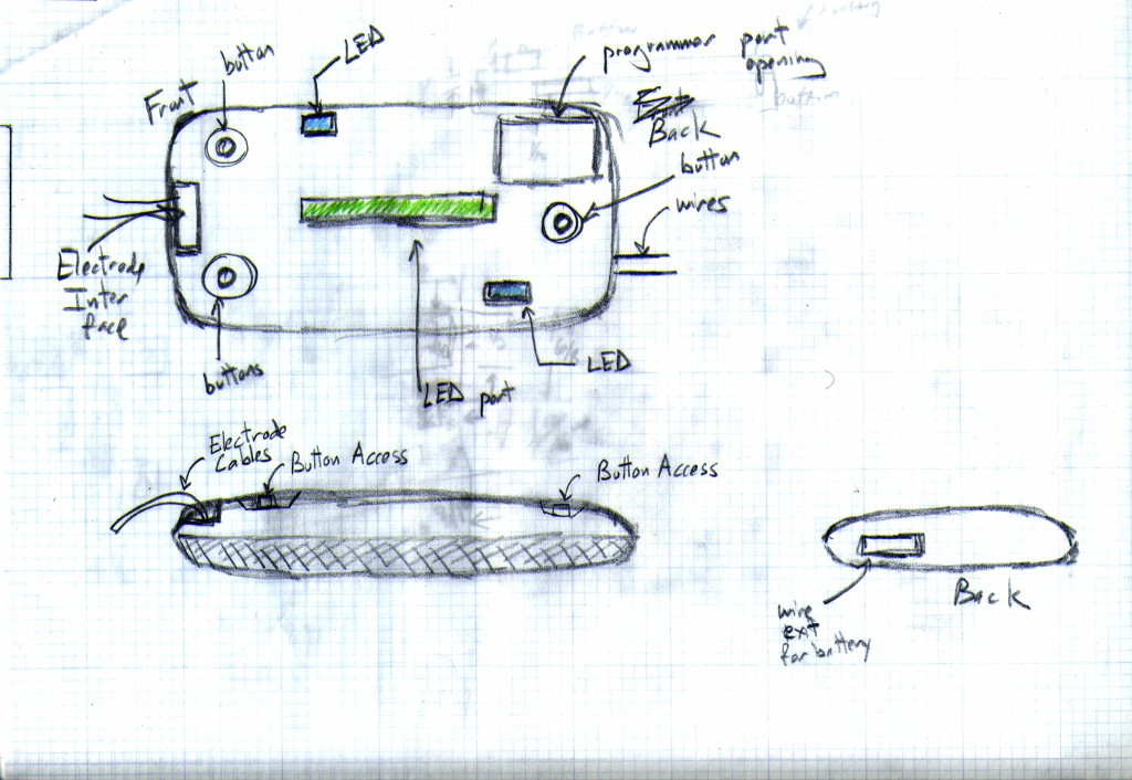
The "pod" is designed to be small, and easy to velcro on to any garment. The back of it is hot glued to a velcro strip (the hook part), while the garment has the velcro furry part. It leaves button access to adjust the gain, and access ports for the programmer to access, and for the electrode wires.
A friend of mine had it 3D printed. And this was the result.
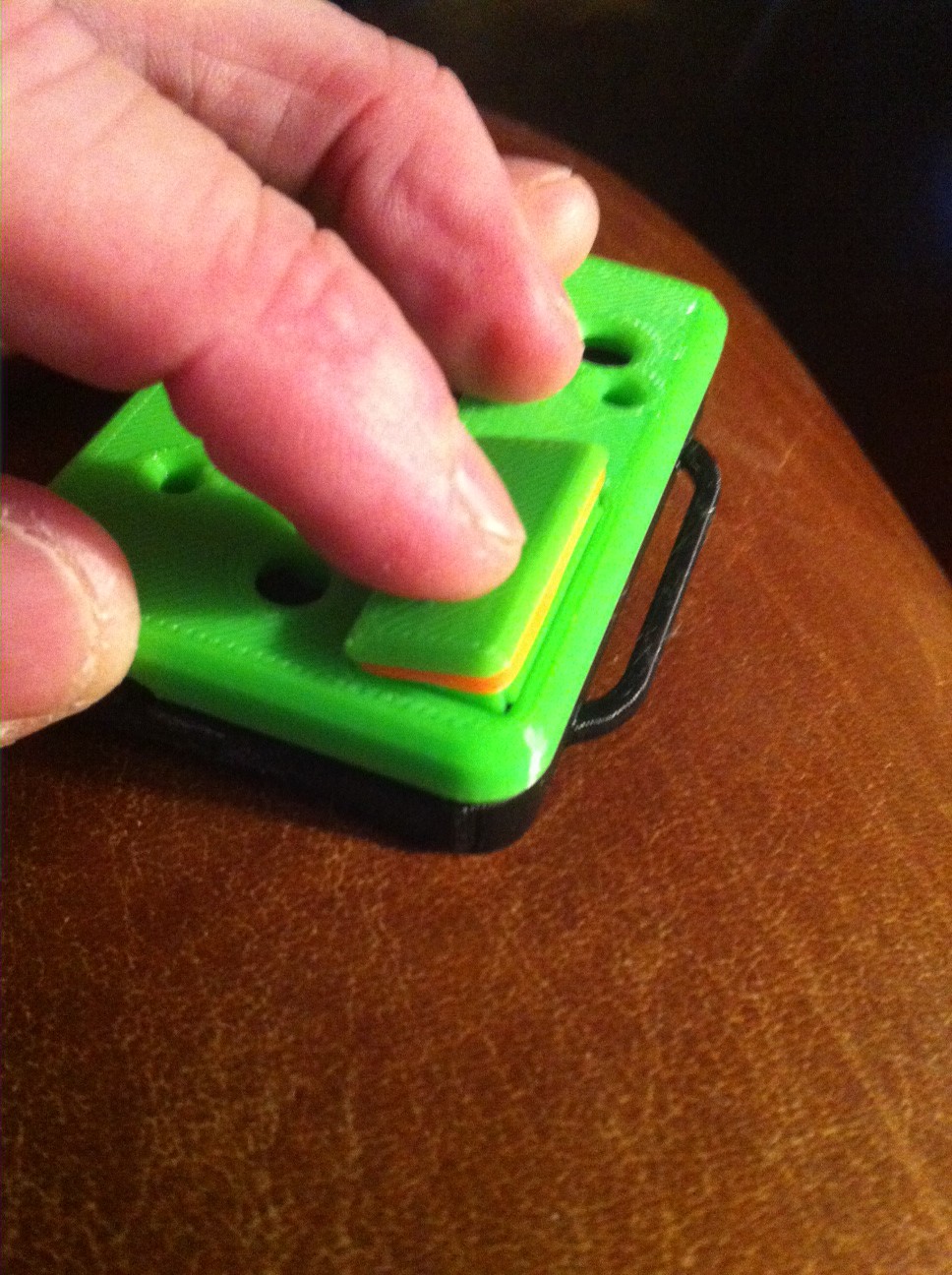
We soldered on the wires and attached a set of disposable electrode pads, and I hot glued a velcro backer to the pod so I can attach it to any of my bicycle clothes. Because when you're creating a wearable, obviously it's gotta go on someone wearing tight pants/shirts. Yeah...
Anyway, here's the end result.
Coming up next, The School of Hardware Startup Hard Knocks Lesson 2, and the Amazingly reconfigurable SEMG sensor pod!
Discussions
Become a Hackaday.io Member
Create an account to leave a comment. Already have an account? Log In.