I've been looking for a project with a real use case for a while now, but most ideas I came up with didn't really make it far. A couple weeks ago it came to my mind that that room, which still has that makeshift lighting I installed years ago, could finally need some proper lighting, and I want to control it using HomeKit (or any home automation really), since that's what the cool kids do these days, right? And what better lighting is there than LED strips? So a project idea was born: Build a controller board for dimming a couple of light strips for the good part of an entire room, and have it controllable over WiFi. It should have enough channels to allow for a few independent RGB groups next to standard white lighting. I'm sure this is nothing groundbreaking, but great for learning and doing it as "proper" as I can.
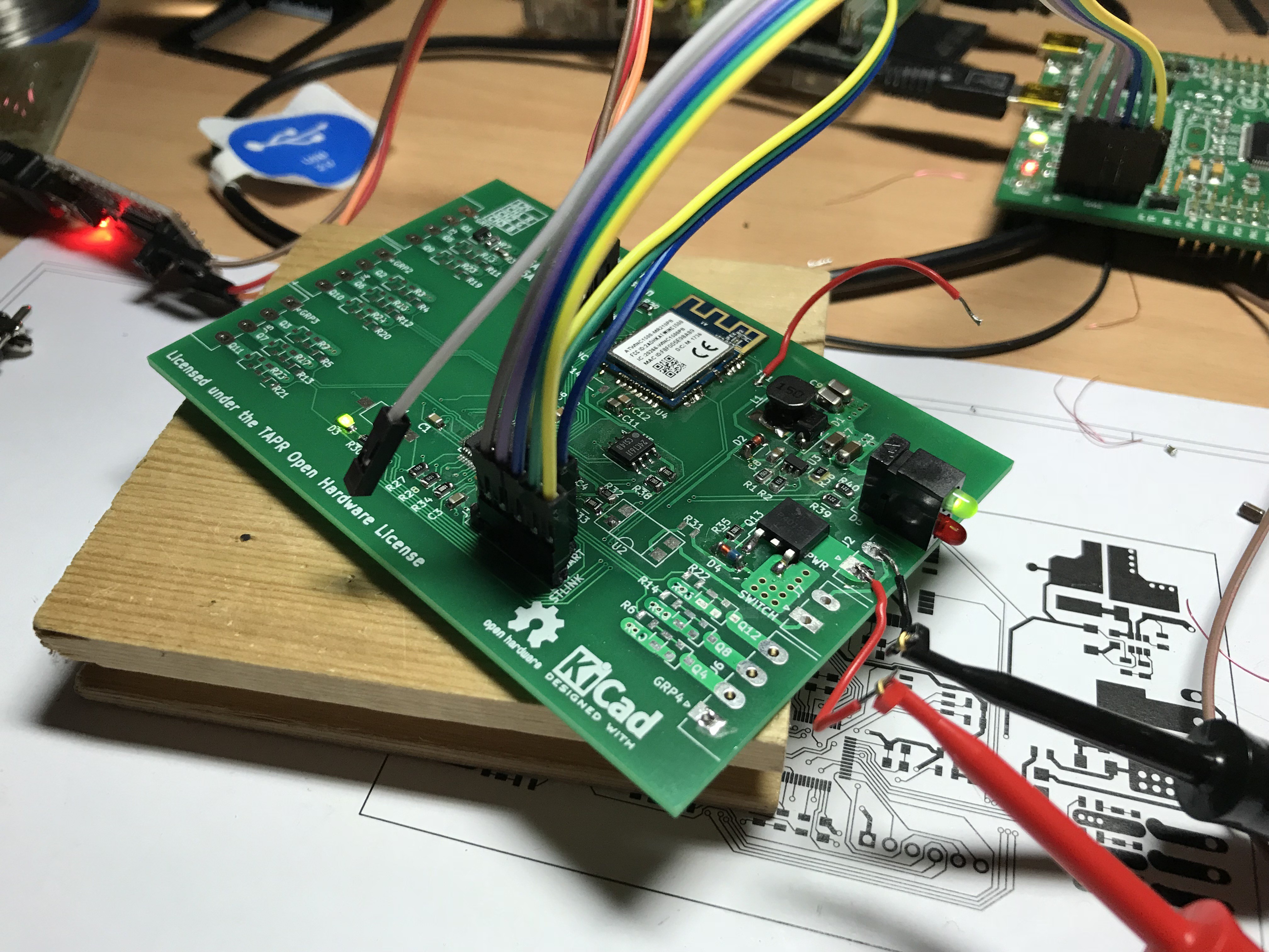
The project is based around a STM32F1 microcontroller hooked up to a ATWINC1500 WiFi module. The choice of micro was a no-brainer, I've been fiddling with a dev board for a while now and it's a good time to actually use one of these chips.
As for the WiFi module, I was kinda torn which direction I should go. Most would probably think of an ESP module as a first choice, but I dislike those various reasons. My first idea was to have a Raspberry Pi Zero W as a "daughterboard", which offers plenty of processing power and, of course, a working network/wireless stack, and can be hooked up using SPI. But the more thought went into this, the less I was convinced it's a good idea, first of all it's quite a chunky device which requires quite a bit of current, and it's overkill in almost every aspect, not to mention the possible instabilities with dying SD cards and whatnot. Then there was this module by Atmel, the ATWINC1500. It's a module which integrates both the WiFi and TCP/IP stack and can be hooked up via SPI to a relatively incapable host MCU. I actually had a look at this module a while back already, but never really had a use case. So that's the route I went with, quickly ordered one from Mouser and built my project around that.
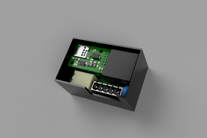
As a fan of industrial equipment, the board uses 3,81mm Phoenix Contact connectors all around. These are rated for 8A 150V, plenty for this use case. Only the main power connector could be a little bigger. A couple meters of LED strips, especially the RGBW ones I have, require quite a lot of current (4,5A@12V/5m at full brightness), but I guess it'll be fine for now.
Each of the 12 outputs is individually controlled by a hardware PWM channel, which could theoretically provide up to 16 bit resolution. In practice, no more than 12 to 14 bit is realistic when trying to achieve decent frequencies. A switching frequency above 3kHz is recommended according to the Wikipedia article on the Flicker fusion threshold and an article by the IEEE Power Electronics Magazine to avoid any affects on humans. At a processor clock of 36MHz, 13 bits of resolution is the maximum to stay well above this threshold and provides a good amount of headroom (8,192 steps) for applying gamma correction:
As a little bonus, I also included an opto-isolated input terminal for attaching a switch, which will be equally exposed over MQTT for integration into a home automation system. Since I don't know any decently priced and technically adequate wall switches I thought this might be a nice addition, always pulling out your phone to turn the lights on might turn out to be a little annoying after a while.
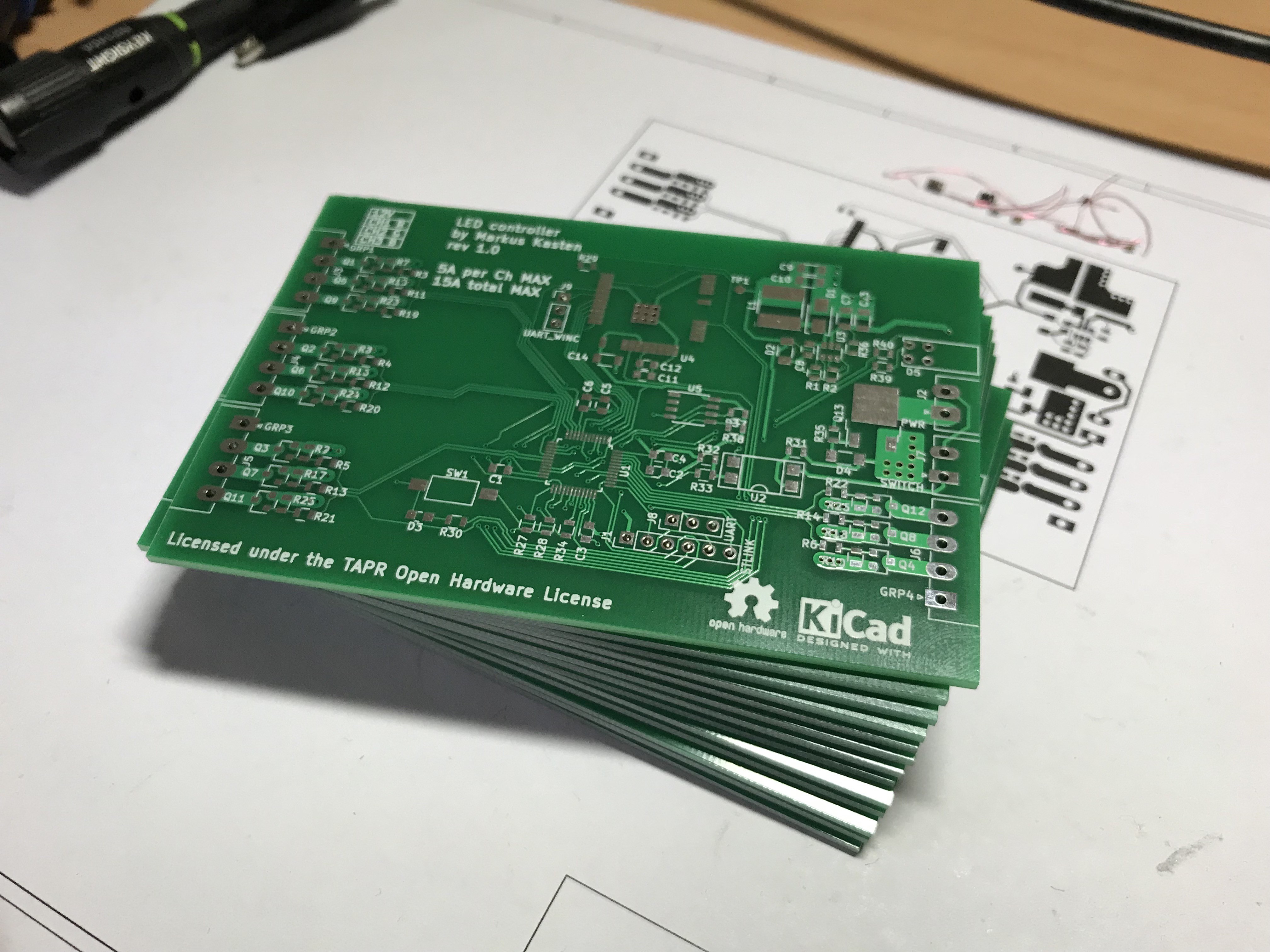
The entire schematic and board layout was created in KiCAD and is available under the TAPR Open Hardware License on GitHub. The firmware is built on the LGPLv3 licensed libopencm3 library and is also available on GitHub. Both are linked on the left site of this project page.


 Nicolò
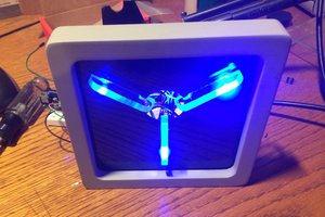
 Beamsjr

 Madison
This is pretty close to something that I would like to see built. Would like to work with someone to develop a 'room control module' - focused on getting switch inputs and PWM of LED lights/strips. Would need to detect click/multi-click, long and dimmer press. House currently uses an Aussie system to control all lights but they are only dim-able from central control panel or App, switches are only latch... If you are still working on this PM me. Cheers Rob