Just a quick update on the PCBs. My parts arrived yesterday and I began assembling and testing the first PCB today. So far there were no major issues with either the parts or the boards. The only small problem I have found so far is my optocoupler footprint, which is a millimeter or two too short, but thats fixable by bending the pins slightly inwards.
All soldering was done using a normal soldering iron with a range of tip sizes and 0.5mm solder, no fancy solder paste and reflow process for now.
I started with populating the buck converter/power supply. I never worked with this particular regulator chip before, so I was quite happy it worked on the first try. My design and layout was mostly based on whats recommended in the datasheet, giving it a good chance of working. I made some very basic ripple, load and efficiency measurements while no other parts were soldered to the PCB, which all gave satisfying results. I got around 80% efficiency, which is slightly below the datasheet values, but my measurements weren't the most precise ones either.
Further on, I soldered the microcontroller and all it's passives on the board. I must have made a slight mistake on one side of the QFP as I broke a couple of it's pads when removing some excess solder afterwards. Luckly all those pads traces went under the chip rather than outwards, and straightening out the loose pads with a sharp needle seemed to have mitigated the problem so far.
With the most essential components in place I started getting my firmware compiled and flashed for the STM32F1. There were a couple of gotchas with the pin remappings for the JTAG, SPI and PWM outputs, but I guess I was lucky it worked out in the end. I didn't went all too deep in the datasheet when assigning the pins in the schematic, and haven't worked with an F1 before, so I was a bit surpised it was that different from an F3.
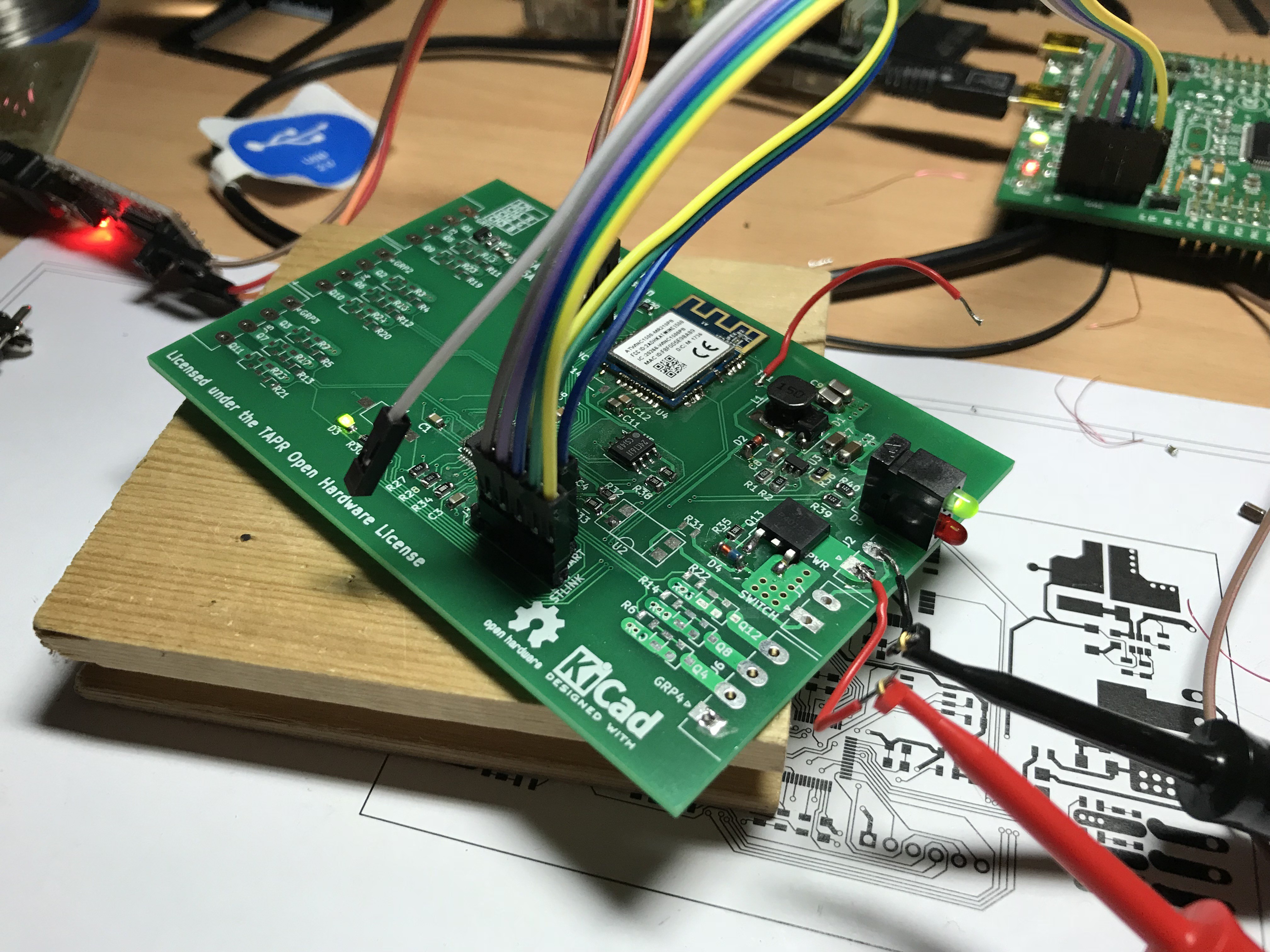
Getting the WiFi module soldered on with it's thermal pad on the bottom was a little tricky, but after a few tries I actually got it in place and without any shorts between the pins. I reused the one I made the adapter since I only ordered one so far, nice to see it survived being soldered multiple times.
At this point, everything that worked on my dev board works in the real board by now. I think I can call myself super lucky there were no fatal shorts, on the first PCB I ever had manufactured :-) Most output MOSFETs aren't fitted yet, I left that open for later when I know there aren't any showstoppers left. Getting the firmware into a usable state is the only big remaining todo now. Having the whole stack of WiFi + MQTT + hardware work properly and avoiding a big spaghetti mess in the meantime turned out to be a bit harder than I initially thought (hoped), but it'll get there. Hopefully next week (I said that like a month ago..).
Discussions
Become a Hackaday.io Member
Create an account to leave a comment. Already have an account? Log In.