 Ted Yapo
Some audio adapters use AC coupling (i.e. an output capacitor), while others work down to DC. The difference for audio is subtle, but for a vector display, it's huge. Here's an illustration using a DC-coupled adapter and the AC/DC switches on the scope inputs.
With an AC coupled output, the centroid of the image will always be in the center of the screen - you can't have a single object translate around, for instance. This happens because the DC (and low frequency) components of the signal that represent the translation of the object are blocked by the output capacitor. You can see the difference in the video.
The dots in that video are another story - for another log.
Solutions
1. Hack Your Pi
The audio output of the Raspberry Pi is AC-coupled, as shown in the schematic:
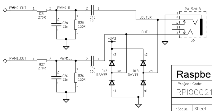
To make the output DC-coupled, you could just short out C48 and C34. Also interesting is the fact that the audio outputs are just PWMs.
2. Buy a USB Audio Adapter
I have been playing with this one. I bought it years ago, so don't know the exact model.
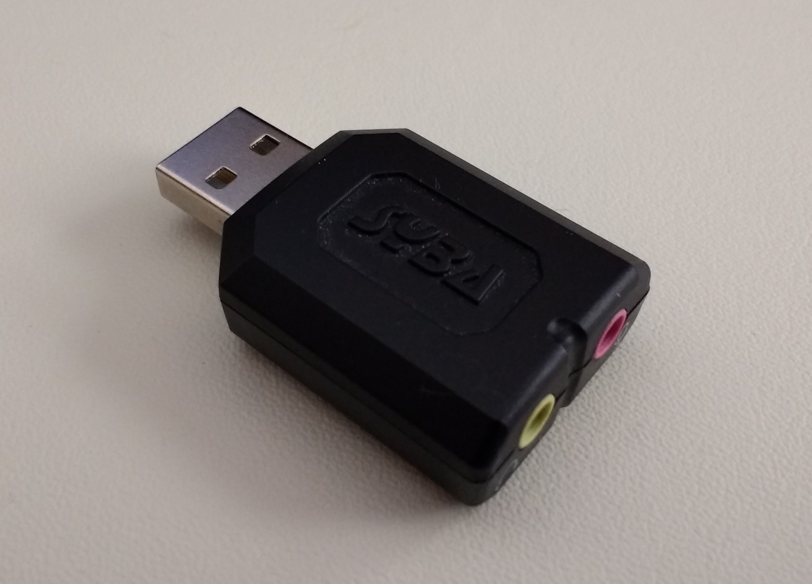
It has an unfiltered DC-coupled digital output, so draws discrete dots instead of lines. Interestingly, it also interpolates extra points into the output (discussed below). New ones like this cost around $8. I'm looking at 96kHz output versions, which are a little more expensive, but will produce a better display.
Beyond possibly higher sampling rates, there's another advantage to a USB adapter: you can use the on-board audio output for game sound effects.
3. Use Software Compensation
I developed some example code that compensates for the removal of the DC components by adding a single repeated extra point to the display. This point, which is always along one of the edges, is calculated so that the centroid of the total display is always at (0,0). Here's an example:
The very bright point at the edge of the display is the extra one added to balance the output. The extra "flying dots" are an artifact of that particular USB audio adapter. Even though it only accepts 48kHz maximum sampling, it appears to interpolate up to 96kHz (and in some cases 192kHz) before output. I don't really understand it yet. More about that in another log.
As you can see, this is workable, but is probably not the preferred solution. I can add a switch in the software to enable it or not.
Discussions
Become a Hackaday.io Member
Create an account to leave a comment. Already have an account? Log In.