 Matt
MattLooks like my boards aren't here for the weekend. Oh well. Thanks to Hackaday for the OSHPark voucher, really appreciate it. While I'm waiting, I've made another small board up. I'm starting to get quite a collection on my desk. I've decided to build up a specific programmer for my ESP boards I'm making. There isn't really any reason for it other than for a bit of fun. Hopefully though it does make life a bit easier in the future if I am programming a bunch of them at once. It has a discreet voltage regulator unlike the sparkfun FTDI Basic board, which means no need for an external power supply anymore (hooray!). I've also broken out GPIO0 on the header, which means i can put a 10k pullup resistor on that pin on the main board, then when i put the programmer on it, it pulls it to ground. It should work i think! I was thinking of using a non standard header size, but i think in the end it'll just cause me more grief than it's worth.
Anyway, here it is.
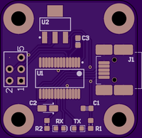
It is based off the DP3030 Sick of Beige board size. It uses an FTDI FT232RL USB-UART IC for its brains, and has an LM1117 3.3v voltage regulator to be able to provide the appropriate amount of power to the ESP8266. Using the voltage regulator in the FTDI chip itself is not a great idea. I've used a 6 pin 2.54mm header and dropped pin 6 out of it. This gives it some polarity so I can't accidentally plug it in the wrong way. I know a whole bunch of people are super keen on Micro USB connectors, but for some reason or other, most of the USB cables I have floating around here are Mini USB, and so that's what I've stuck with here.
Here is a link to the board on OSHPark.
Here is a list of parts required:
U1: FTDI FT232RL SSOP (Be weary of counterfeit chips! Dave Jones says so!)
U2: LM1117 3.3v SOT223
R1, R2: 330R 0603 resistor or there abouts
RX, TX: 0603 LEDs
C1, C3: 100nF 0603 ceramic cap
C2: 4.7uF 3216 Tantalum cap
J1: Mini USB connector
(Unlisted): 3x2 2.54mm header with one of the corner pins ripped out.
As with all my other boards, this is untested so far. I will update this post when I know it works/doesn't work.
Discussions
Become a Hackaday.io Member
Create an account to leave a comment. Already have an account? Log In.