 Paul Kocyla
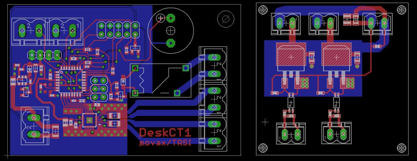
Here is the (hopefully) final control board and power switch board dsign. It´s sent for production.
The controller board contains a relais for the camera trigger, a motor driver for the rotary table, a buzzer to warn you when the x-ray powers up and an interface for the switch buttons and the coil drivers.
The power board contains two isolated power-mosfets to drive the ignition coils and the transformer for the tube´s filament heating.
I decided to put the power board near the ignition coils & filament heater to reduce the EMI on the controller board. The coils spit lots of unwanted EMI, maybe I´ll need to replace the stepdown converter by a simple LDO, because it showed that switching converters get dizzy by the EMI (induction in the switching coils?) Let´s see. Chopping the coils induces high voltages on the primary side( (>400V) which are indended to occur to develop a high enough output voltage, so they should stay on short paths to the battery. Varistors are included for protection of the control board, just in case.
^^ The filament of the vacuum tube should be heated to ensure a higher current flow. Because two ignition coils are necessary to get a voltage that is high enough to generate hard x-rays, there is a potential of up to 30kv on the heated cathode against the supply rails. So if you want to heat up the filament, you can´ t just wire it to the control board. A solution would be inductive coupling by two air coils isolated by a plastic wall.
Discussions
Become a Hackaday.io Member
Create an account to leave a comment. Already have an account? Log In.