-
Connecting up
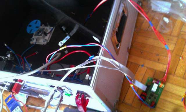
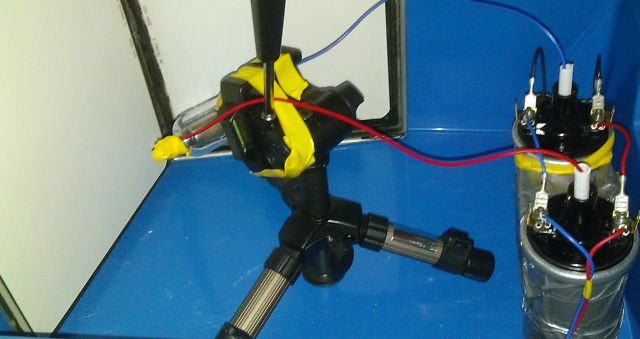
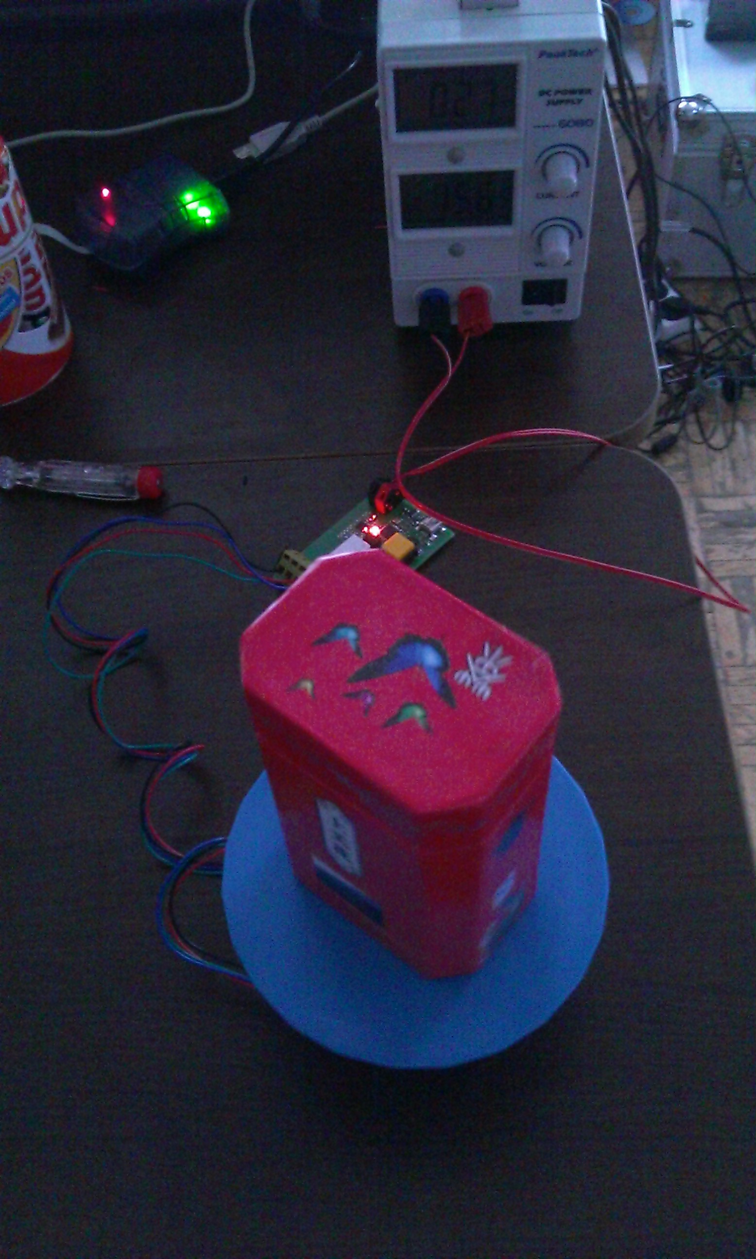
08/08/2015 at 08:30 • 0 commentsMany wires to connect... actually not so many in the end :)
![]()
-
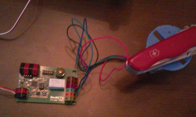
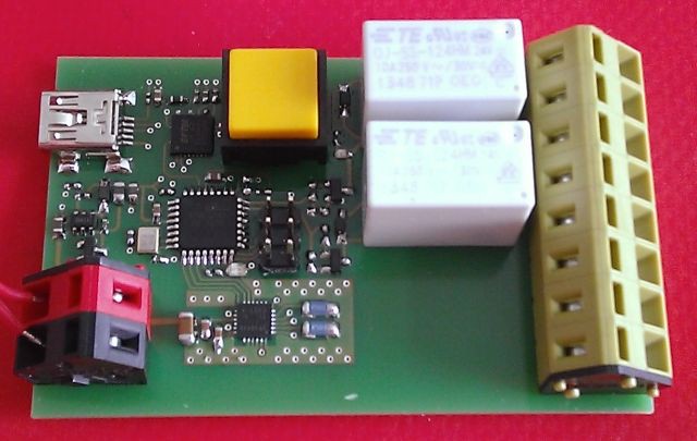
New board soldered
07/30/2015 at 18:30 • 0 commentsNew board soldered and running.
Now I will wire all the system.![]()
-
New control board
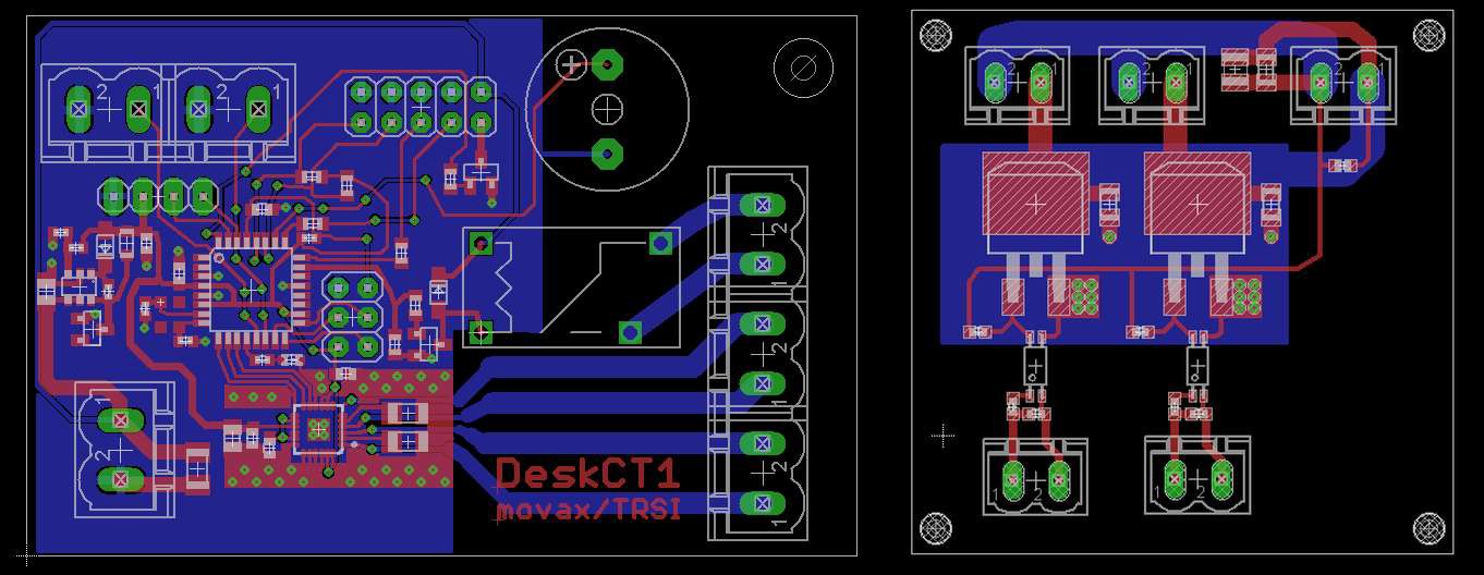
07/13/2015 at 21:11 • 0 commentsHere is the (hopefully) final control board and power switch board dsign. It´s sent for production.
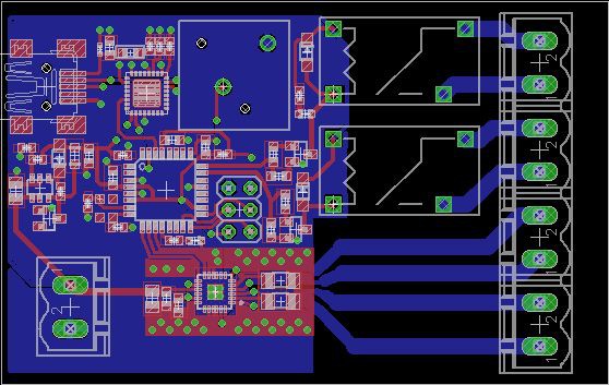
The controller board contains a relais for the camera trigger, a motor driver for the rotary table, a buzzer to warn you when the x-ray powers up and an interface for the switch buttons and the coil drivers.
The power board contains two isolated power-mosfets to drive the ignition coils and the transformer for the tube´s filament heating.
I decided to put the power board near the ignition coils & filament heater to reduce the EMI on the controller board. The coils spit lots of unwanted EMI, maybe I´ll need to replace the stepdown converter by a simple LDO, because it showed that switching converters get dizzy by the EMI (induction in the switching coils?) Let´s see. Chopping the coils induces high voltages on the primary side( (>400V) which are indended to occur to develop a high enough output voltage, so they should stay on short paths to the battery. Varistors are included for protection of the control board, just in case.
^^ The filament of the vacuum tube should be heated to ensure a higher current flow. Because two ignition coils are necessary to get a voltage that is high enough to generate hard x-rays, there is a potential of up to 30kv on the heated cathode against the supply rails. So if you want to heat up the filament, you can´ t just wire it to the control board. A solution would be inductive coupling by two air coils isolated by a plastic wall.
![]()
-
Mounting the Setup
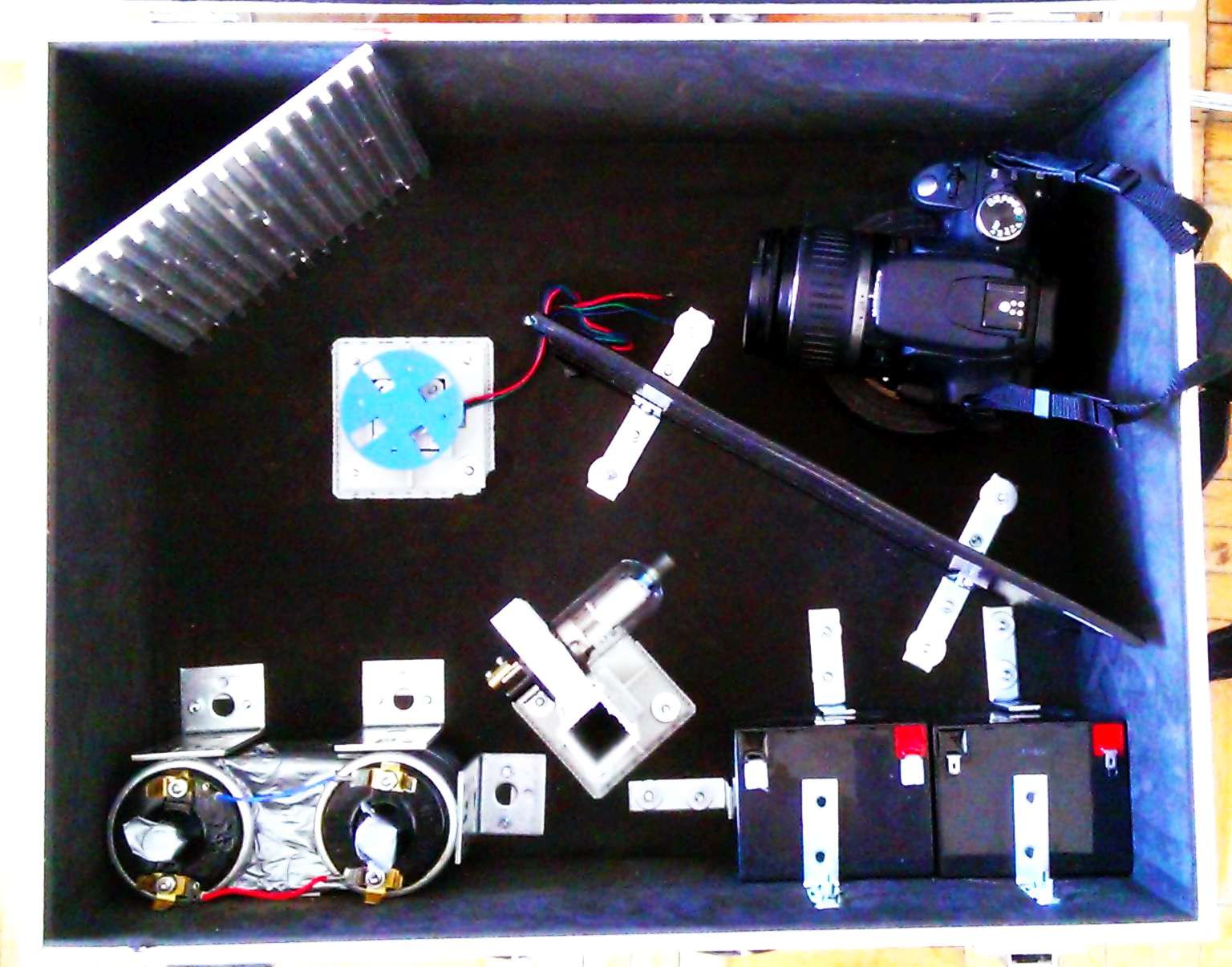
07/10/2015 at 17:18 • 0 commentsMounting of the setup is progressing.
Left upper corner: Plate to which the intensifying screen will be glued
Left lower corner: car ignition coils
Middle low: Rectifying tube
Right lower: Batteries
The camera is protected from the X-Rays by a lead plate
The rotating table is between the screen and the tube
![]()
-
Got X-Rays
06/03/2015 at 21:58 • 0 commentsGot X-RAYS, yeah :-D
It works fine. I get a smooth nice green glow on the scintillator screens.
It works with car engine ignition coils and an old radio tube (there are plenty of them on ebay, from 50 cents to 3€)![]()
-
High Voltage source
05/31/2015 at 11:34 • 0 commentsThe Xray-power source for the 100$ scanner version.
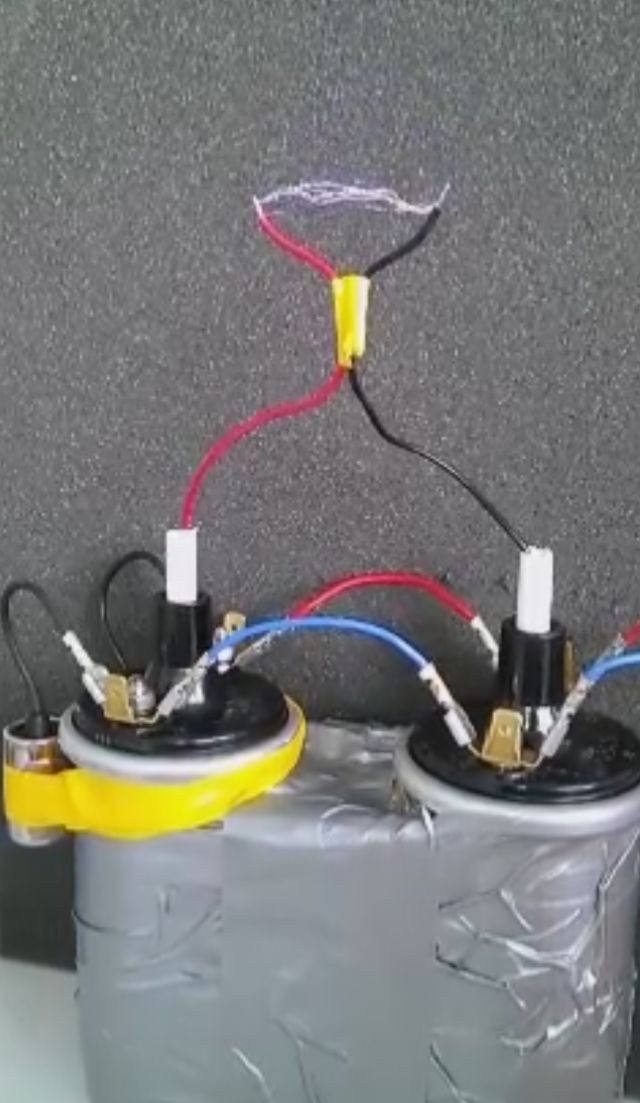
Made of two car ignition coils, which you can even get for free when you´re lucky.I connencted them parallel (in reverse) to double the voltage. It is driven by a power mosfet.
I read some nasty flame-comments about this project, regarding the "100$"-label :-D
YES, this version WILL cost at max 100$. The other version with the commercial x-ray source is an additional bonus, but of course I want to make this project replicable for everyone.![]()
-
Rotary Table Working
05/16/2015 at 17:12 • 0 commentsThe board was working out of the box - nice :)
![]()
-
Controller Board Soldered
05/16/2015 at 10:40 • 0 commentsThere it is - finally soldered.
It contains a new motor driver from TI, an USB connector and two relais.
I chose an ATMega8 as MCU. This will also make the board arduino compatible.
![]()
-
DESKTOP CT: rotary table, xray source
04/24/2015 at 22:19 • 0 comments![]()
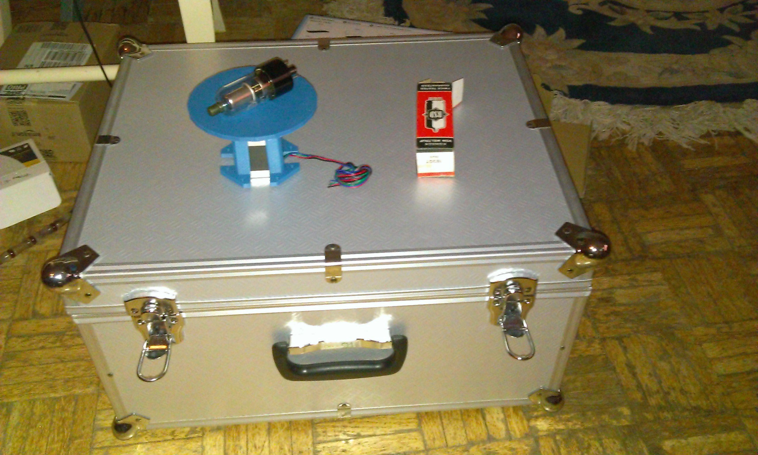
The aluminium box will be the mobile CT scanner case. I printed a rotary table and a NEMA17 stepper motor holder for the object to scan.
The electron tube (a diode) will serve as an x-ray source. -
Control Board Design finished
03/21/2015 at 09:50 • 0 commentsJust finished the Control Board design for the CT scanner. It´s based on an ATmega8 from Atmel.
It uses a small form factor microstepping IC from TI with 1A current capability to drive the rotary table.
Relais are included to control the X-Ray generator and the digital camera.
An USB connector enables a terminal connection to parametrize the control board with a PC.
Finally there is a switch to START/STOP the scan and two status LEDs.
![]()
 Paul Kocyla