 OpenBionics
-
Low-Cost, Off-the-Shelf Materials, Tools and Rapid Prototyping Techniques
09/21/2015 at 05:40 • 0 commentsAll the different hand parts are created using off-the-shelf, low-cost materials that can be easily found in hardware stores around the world. For example the low-friction tubes can be substituted with common swabs used for ear cleaning, by removing the parts covered with cotton.
The materials that are used for creating the prosthetic hand are the following.
Prosthetic Hand Materials
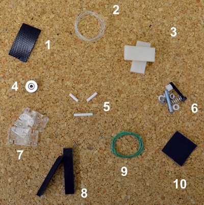
1. Rubber Splicing Tape 2. Nylon Fishing Line (0.4mm)
3. Silicone Sheets, width: 4mm, 5mm, 6mm
4. Deep v-groove (1.2mm) sealed pulley rail ball bearings
5. Low friction tubes (e.g., ear cotton swabs)
6. Various Nuts, Sockets, Rods & Washers
7. Plexiglas Sheets, width: 2mm, 4mm or ABS for 3D printed version.
8. Foam Tape (4.5mmx10mm)
9. Dyneema Fishing Line (0.4mm)
10. Antislip Tape
All materials appear in the following image with the corresponding numbers.
![]()
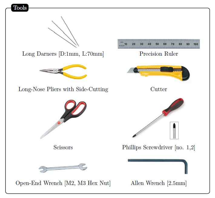
The tools required for the construction of our prosthetic hand are depicted in the following figure.
![]()
Two different materials have been considered for creating the different hand parts, Plexiglas (acrylic) and ABS.
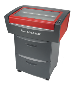
For the version created with the laser cutter, we used Plexiglas (acrylic) because it is low-cost, light-weight, it can be easily found, it has good durability, significant ultimate tensile strength (8.500 - 11.250 psi) and almost the same density (1.19 gr / cubic cm | 0.043 lbs / cubic inch), with other common plastics like ABS. The laser cutting machine used, was the Universal Laser Systems VSL 3.5 that appears in the following image. The estimated fabrication time with the laser cutter is ~ 2 hrs.
![]()
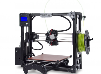
For the 3D printed version we used ABS and more precisely red and white 3 mm filaments with the Lulzbot TAZ 4, 3D Printer that appears in the following image. The estimated fabrication time with the 3D printer is ~ 6 hrs.
![]()
It must be noted that the hereby proposed design can be implemented with any kind of plastic or any other material available. We plan also to develop an aluminium version and test it.
-
Parametric CAD Files
08/09/2015 at 19:04 • 0 commentsParametric CAD Files
We provide appropriate CAD files (Solidworks .sldasm, .sldprt and .dwg, .dxf, .stl), for the replication of the proposed design.
The latest version of our parametric CAD files can be found in our GitHub repository:
OpenBionics GitHub Repository.
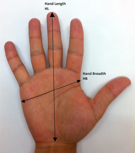
Τhe use of parametric models derived from human hand anthropometry studies, allows for the development of personalized prostheses. The only parameters that we need in order to derive the finger phalanges lengths and the personalized finger base frames positions and orientations, are the human hand length (HL) and the human hand breadth (HB).
We have modified our CAD files in order to integrate the required parameters (HL & HB) for the replication of a personalized design. First, you need to decide which hand you want to replicate (Right or Left). You can find below a quick guide for the production of the personalized design. The procedure is the same for both hands.
- Open the file "prostheticParameters.SLDPRT" which can be found @ Prosthetic-Hands\CAD\Left.
- Make the "parametersSketch" file editable. You can see there, the parameters that you can change. Their values are reported in mm and NOT in inches.
- Open the assembly file "AnthropomorphicHandAssembly.SLDASM" which can be found @ Prosthetic-Hands\CAD\Left\Assembly.
- Go to the part file "prostheticParameters.SLDPRT" and change the desired values (HL=hand length, HB=hand breadth & fingerWidth) according to this image and then save the file.
- Go to the assembly file "AnthropomorphicHandAssembly.SLDASM" and rebuild it. All .SLDPRT files that are used in the assembly should be rebuilt.
- If you want .STL files you should open every rebuilt part and then choose "Save as .STL".
Things to note:
- The design has specific constraints which cover the 95th percentile of human hand and those are:
Hand Length: 182 - 225mm
Hand Breadth: 82,5 - 110mm. - Dimensions should be changed symmetrically. The mean HL/HB ratio is 2.2, so if your new assembly has errors it is probably either because you didn't measure correctly your hand values or because your hand construction is very far from the mean human value.
- For editing our CAD files you should own Solidworks 2014 or a later version. In case you don't have access to the required software, complete this webform in the OpenBionics website. We are working on a project, in order to further modify our design with open-source CAD software.
- Our approach is inspired by the Yale Open Hand project. More details can be found here.
- An assembly guide and a video tutorial will soon be available.
-
Personalized Designs
08/09/2015 at 18:54 • 0 commentsΤhe use of parametric models derived from human hand anthropometry studies, allows for the development of personalized prostheses. The only parameters that we need in order to derive the finger phalanges lengths and the personalized finger base frames positions and orientations, are the human hand length (HL) and the human hand breadth (HB). More information regarding the hand anthropometry studies and the parametric models can be found in [1] and [2].
The importance of the personalization feature that we provide becomes really significant, considering the fact that customization of commercially available solutions to the body of each individual, typically leads to additional costs of thousands of dollars.
![]()
You can use the following link to order your personalized design (.CAD files):
Web Form for Personalized Designs![]()
References
[1] B. Buchholz, T. J. Armstrong, and S. A. Goldstein, “Anthropometric data for describing the kinematics of the human hand,” Ergonomics, vol. 35, no. 3, pp. 261–273, 1992.
[2] M. V. Liarokapis, P. K. Artemiadis, and K. J. Kyriakopoulos, “Quantifying anthropomorphism of robot hands,” in IEEE International Conference on Robotics and Automation (ICRA). IEEE, 2013, pp. 2041–2046.
-
Results / Experiments
08/09/2015 at 18:07 • 0 commentsOverview
The first set of experiments focuses on validating the efficiency of the proposed selectively lockable differential mechanism to implement different postures and gestures, using only one motor. The second set of experiments focuses on grasping a wide range of everyday life objects, to execute daily living activities.
In order to validate the efficacy of the proposed design we performed multiple experiments that included: 1) grasping of a wide range of everyday life objects, 2) execution of a series of daily living tasks. For doing so, we used an Arduino Micro platform [1] to control the HerkuleX DRS0201 servo motor, a custom made PCB module that connects the Arduino platform with the servo motor and the ROS package (written in Python), that we created within the context of the OpenBionics initiative.Force Exertion Capability
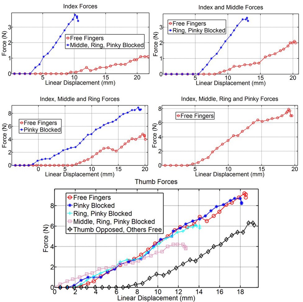
We conducted an experimental analysis of the force exertion capability of the hand in different grasping postures. In Fig. 1, we present the relationship between the tendon displacement and the forces exerted by different combinations of fingers. As it can be noticed, by blocking different combinations of fingers we are able to maximize the force applied by the fingertips of the free fingers (for precision grasps). PIP joint has a bigger range of motion as it is implemented with 4 mm silicone sheet (to optimize Kapandji test [2]). If we want to use a grasp involving less than five fingers, we can block the subsidiary fingers and maximize the force transmitted from the servo motor to the active fingertips.
![]()
Fig. 1. Relationship between the tendon displacement and finger forces for different grasping postures.
Implementing Different Grasping Postures and Gestures
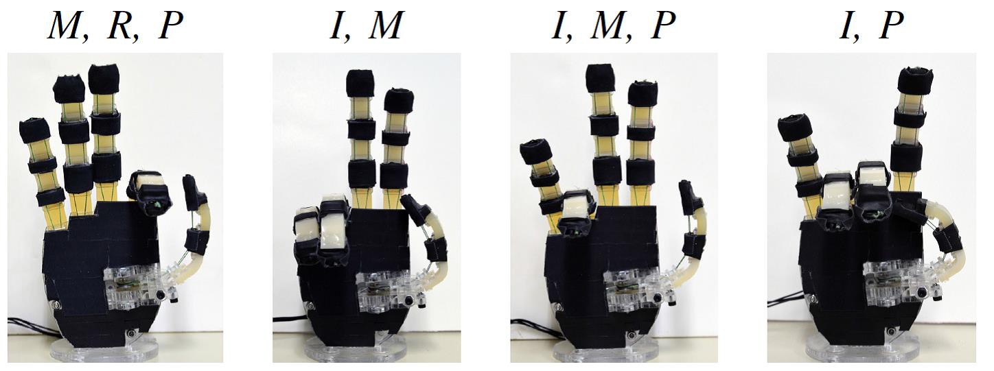
The first set of experiments focuses on validating the efficacy of the proposed selectively lockable differential mechanism. For doing so, the user presses the different buttons locking different combinations of fingers. Such a functionality is not only important for grasping (where the user is able to choose the preferred grasping strategy / posture), but also for: 1) implementing specific gestures (e.g., making the peace sign or showing a number), 2) reaching an object located at a narrow space (task that may require less than five fingers), or 3) execute non-prehensile manipulation tasks (e.g., press a button or move a slider on a console). In Figs. 2 and 3 different postures are depicted. The motion of each locked finger is constrained by the corresponding button of the differential mechanism.
![]()
Fig. 2. Four different postures are depicted. All fingers except one are closing. The locked finger can be used to: 1) press buttons, 2) to reach something in narrow spaces, 3) to implement specific gestures or 4) to execute non-prehensile manipulation tasks (e.g., moving a slider).
![]()
Fig. 3. Four different postures are depicted. The differential mechanism allows for different grasping postures and hand gestures to be achieved. With the letters I, M, R and P we denote that motion of the index, middle, ring and pinky finger respectively, is constrained.
Grasping Everyday Life Objects
The second set of experiments focuses on grasping a wide range of everyday life objects, to execute daily living activities. The objects used are: 1) a mug, 2) a soap, 3) a magazine, 4) a marker, 5) a pair of glasses, 6) a large rectangular box, 7) a glass cleaner spray, 8) a 1.5L bottle of water, 9) a glass of water and 10) a spoon. Regarding the daily living tasks, the hand is used: 1) to serve water from a 1.5L bottle to a glass, 2) to stir the water inside the glass with a spoon and 3) to position a series of tools to their cases and put them inside a rectangular box. Instances of the conducted experiments, can be found in Fig. 4.
![]()
Figure 4. Images from the experiments conducted. Five different everyday life objects are grasped in order to execute different tasks: 1) a coffee mug is grasped from the handle in order to drink from it, 2) a marker is grasped in order to write, 3) a pair of sunglasses is picked up and 4) a 1.5L bottle is grasped in order to serve water.
All experiments were recorded and the video can be found (in HD quality), at the following URL: http://www.openbionics.org/videos/
References
[1] Arduino, “Open-source electronics prototyping platform based on microcontroller,” http://www.arduino.cc, Aug. 2015.
[2] I. Kapandji, Physiology of the Joints: Upper Limb: Volume 1. Churchill Livingstone Edinburgh, 1974.
-
Actuation / Transmission Mechanisms
08/09/2015 at 18:06 • 0 commentsIntroduction
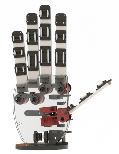
In our hand, actuation is generated with only one motor and transmitted through tendon routing to the fingers with two separate, decoupled mechanisms: 1) A locking mechanism for the thumb and 2) A selectively lockable differential mechanism for the rest of the fingers. Two different tendon routing systems are used, each terminated to a different pulley, connected to the motor. The thumb pulley allows for smaller motor angular displacements to produce similar joint angle displacements with the other fingers. The diameters of the pulleys were selected to be the ones that score best in the Kapandji test [1].
![]() Thumb Locking Mechanism
Thumb Locking MechanismThumb opposition is implemented using only one rotational DoF instead of three as in the human hand, thanks to the locking mechanism on which the thumb is mounted. This is a selectively lockable toothed mechanism that allows the orientation of the base frame of the thumb to be locked on 9 different angles. The choice for the 9 discrete positions was made so that the hand is able to attain the configurations described in the Kapandji test [1], allowing the user to switch between different grasping strategies, according to the task to be executed (e.g. key grasp or full grasp). The position of the base frame of the thumb and its range of motion, were derived in an anthropomorphic way following the methodology described in [2]. The proposed mechanism is completely stiff when locked, in contrast to friction based mechanisms [3] that are affected by torsional forces inherent in dynamic / unstructured environments (these forces can result to large, uncontrolled displacements of the thumb for these mechanisms).
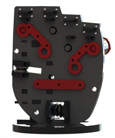
Selectively Lockable Differential Mechanism
For the rest of the fingers, actuation is transmitted through a differential mechanism which is essentially a variation of the whiffletree [4]. Our whiffletree consists of three bars: one bar connecting the index and middle fingers (bar1), one bar connecting the ring and pinky fingers (bar2) and the main bar that connects bar 1 and bar 2. This design allows only one motor to control multiple fingers in a coordinated fashion: a small linear displacement of the tendon causes a proportional angular displacement at all robot joints. This way, even upon contact of one finger with the environment or the object surface, the motion of the fingers that remain unconstrained is not blocked but facilitated.
At the same time, the mechanism allows the user to pick different configurations in an intuitive manner: The top two bars have appropriately designed holes and the palm accommodates a set of buttons that upon pressing are elongated. When a button is pressed the elongated part fills the corresponding finger hole and the motion of this particular finger is constrained. A total of 2^4 = 16 different finger combinations can be implemented using the differential mechanism and a single motor, which combined with the 9 discrete positions of the thumb, produce a total of 144 different grasping postures.
The major advantages of this mechanism are its dexterity (144 grasping postures), achieved with only one motor and its simplicity of use (simple buttons allow for intuitive switching between different postures). Our design outperforms other implementations of the whiffletree [3] on hand design through its low mechanical complexity, ease of fabrication and intuitive use.
References
[1] I. Kapandji, Physiology of the Joints: Upper Limb: Volume 1. Churchill Livingstone Edinburgh, 1974.
[2] M. V. Liarokapis, P. K. Artemiadis, and K. J. Kyriakopoulos, “Quantifying anthropomorphism of robot hands,” in IEEE International Conference on Robotics and Automation (ICRA). IEEE, 2013, pp. 2041–2046.
[3] M. Baril, T. Laliberte, C. Gosselin, and F. Routhier, “On the design of ´ a mechanically programmable underactuated anthropomorphic prosthetic gripper,” Journal of Mechanical Design, vol. 135, no. 12, p. 121008, 2013.
[4] L. Birglen and C. M. Gosselin, “Force analysis of connected differential mechanisms: application to grasping,” The International Journal of Robotics Research, vol. 25, no. 10, pp. 1033–1046, 2006.
OpenBionics Affordable Prosthetic Hands
Affordable, light-weight, anthropomorphic prosthetic hands, using a novel selectively-lockable differential mechanism.


 Thumb Locking Mechanism
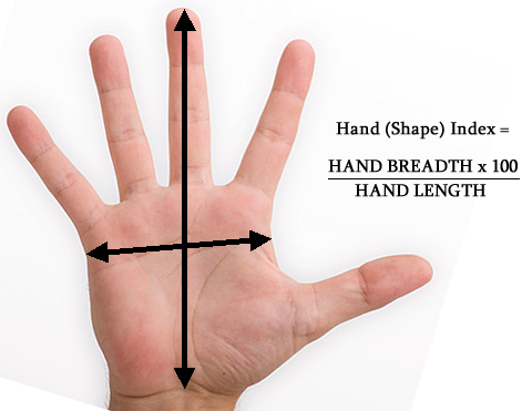