 Gorky
GorkyWell I guess things started taking shape especially after some Easter work. I have made a lot of trials and errors and made some changes to parts and overall system design. Will try to note down my mistakes, what I have learned and decisions made. Hope they help to someone putting together a similar project.
- I decided to use a 6V SLA battery.
- As in this project weight is not a big deal
- SLA charging is forgiving, relatively easy and safe.
- Price
- 6V is kind of a sweet spot relatively easier to regulate down and up.
- I changed 3.3v ldo regulator with a 5v ldo regulator. At first I was thinking mcu will consume less if powered by 3.3v but compared to the power loss based in voltage difference in the regulator going for 5v is better. So
- Less power loss from linear regulation
- LDO I have used has max. 300mv drop out. I will keep the SLA lower voltage limit at 5.5v where lower is no good for the battery anyways. So we have plenty of volts there.
- More devices to chose from when working with 5v instead of 3.3 (such as mosfets, mosfet drivers, op amps)
- I was planning to use buck converter for MPPT. I tried buck, cuk, boost and boost-buck charging 6V SLA with a variety of panels ranging from 0.5W 6V, 2W 6V, 1W 12V, 3W 9V. And I decided to go with boost conversion. Why?
- Considering this projects power requirements lower voltage panels are more suitable as they are relatively cheaper, smaller, easier to obtain and better suited for diy (make your ridiculously high power, low voltage panels)
- Boost converter is the simplest implementation with less number of components compared to other switching topologies. Using a logic level mosfet, no extra driving circuit, charge pump or bootstrap circuit is required.
- It's winter here and it rained for 2 days which might have effected me : )
- I changed the op amp I was using to measure current to MCP6022. While being around 40 cents more expensive it has a much lower input offset voltage which allows a mA level precision current measurement. I also tried a ACS712 based current sensor but I decided not to use it because charge current will be max. 500mA in this project which means tiny loss on shunt resistor also means too little for ACS712 leading to less precision. Besides ACS712 has a 10ma quiescent power consumption which is kind of bothering for a low power project.
And here are some pics. Sorry for the mess as usual
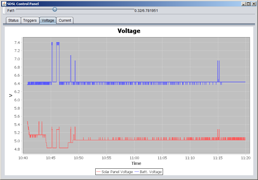
Panel voltage (before boost) and battery voltage (slider adjusts boost pwm duty for debug purposes.) Peaks happened when I disconnected battery to test output voltage of boost converter.
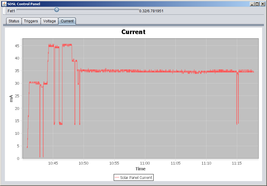
Current, peaks represent times that I was poking in with the multimeter to check it.
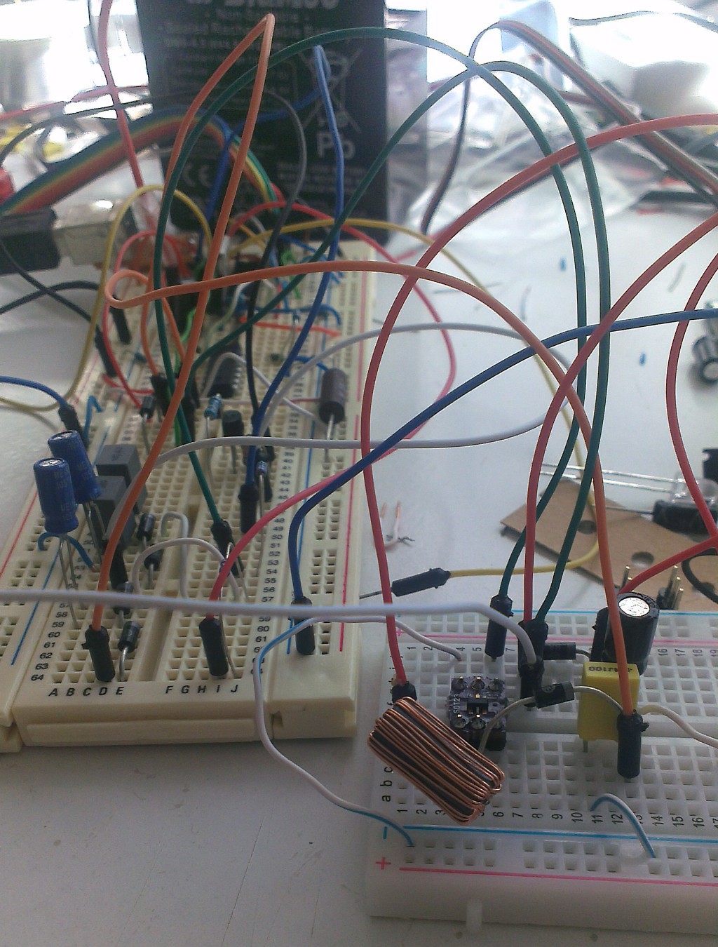
Mess of board populated with torn apart implementations of different converters. And the inductor is levitating!
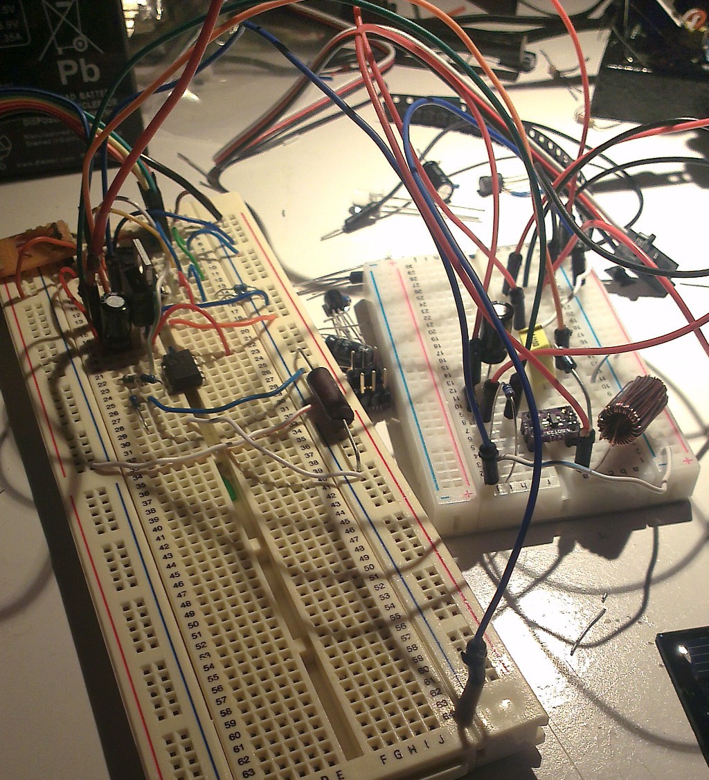
After a bit of cleaning up.
Discussions
Become a Hackaday.io Member
Create an account to leave a comment. Already have an account? Log In.