Specifications
- THD: 0.00190%
- THD+N: 0.01013%
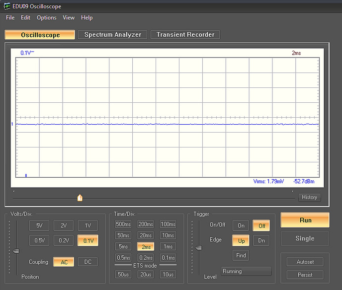
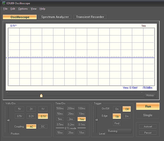
- SNR: 112.83 dB (Shorted inputs, relative to 1 Vrms/0 dBV)
- Crosstalk: -102.24 dB
- IMD: 0.0195% (ITU-R, 19+20 kHz)
- Dynamic Range: >110 dB (THD+N: 1%)
- RIAA Compliance: +/- 0.025 dB
- RIAA Equalization: Passive
- Gain: 36-46 dB in four steps
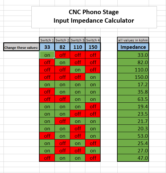
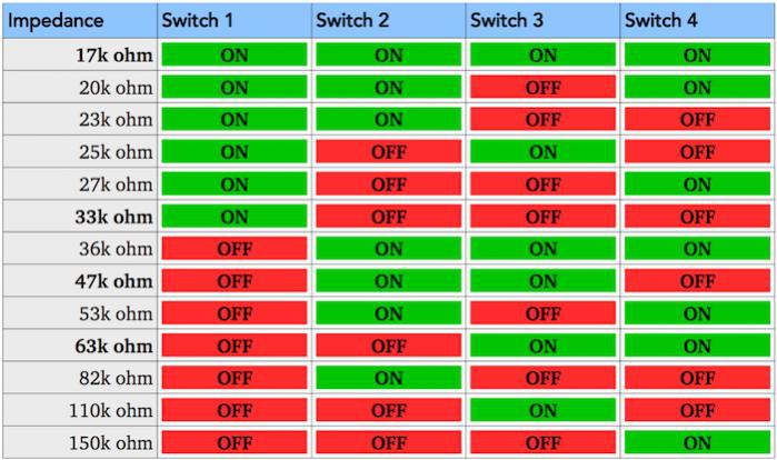
- Input Impedance: 17k-150k ohm in fifteen steps
- Input Capacitance: N/A
- PCB Size: 90 x 51 mm
Background
The AudioKarma CNC Phono Stage started its life on the AudioKarma forums, ignited by user Fasterdamnit:
AudioKarma CNC Phono Stage Thread
This project would not exist without all the work that has been done by the guys that hang out at AudioKarma.
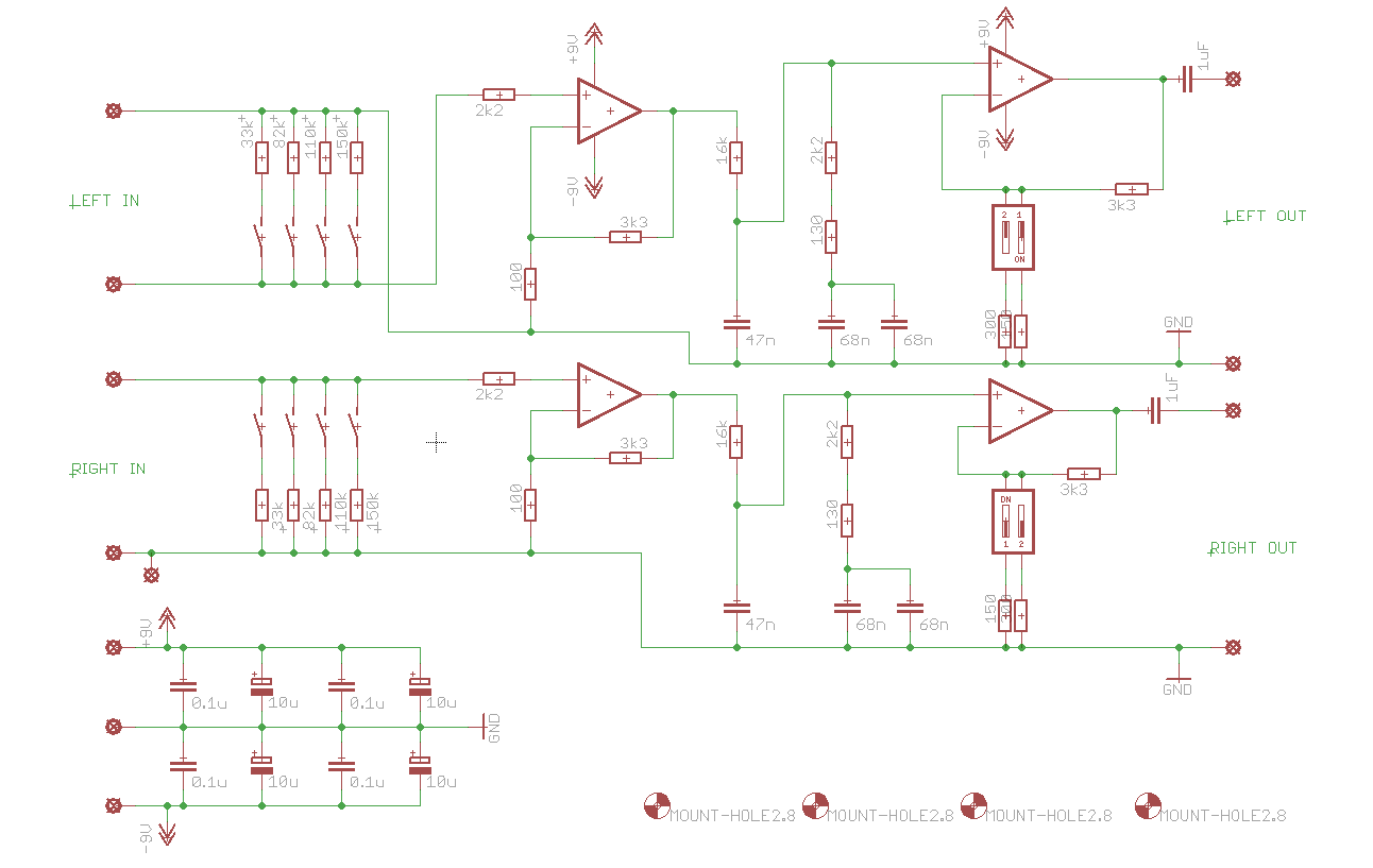
In its original form, it has the following features:
- Input capacitor
- Variable input impedance
- Two opamp gain stages
- Passive RIAA equalization between the two gain stages
- Output capacitor
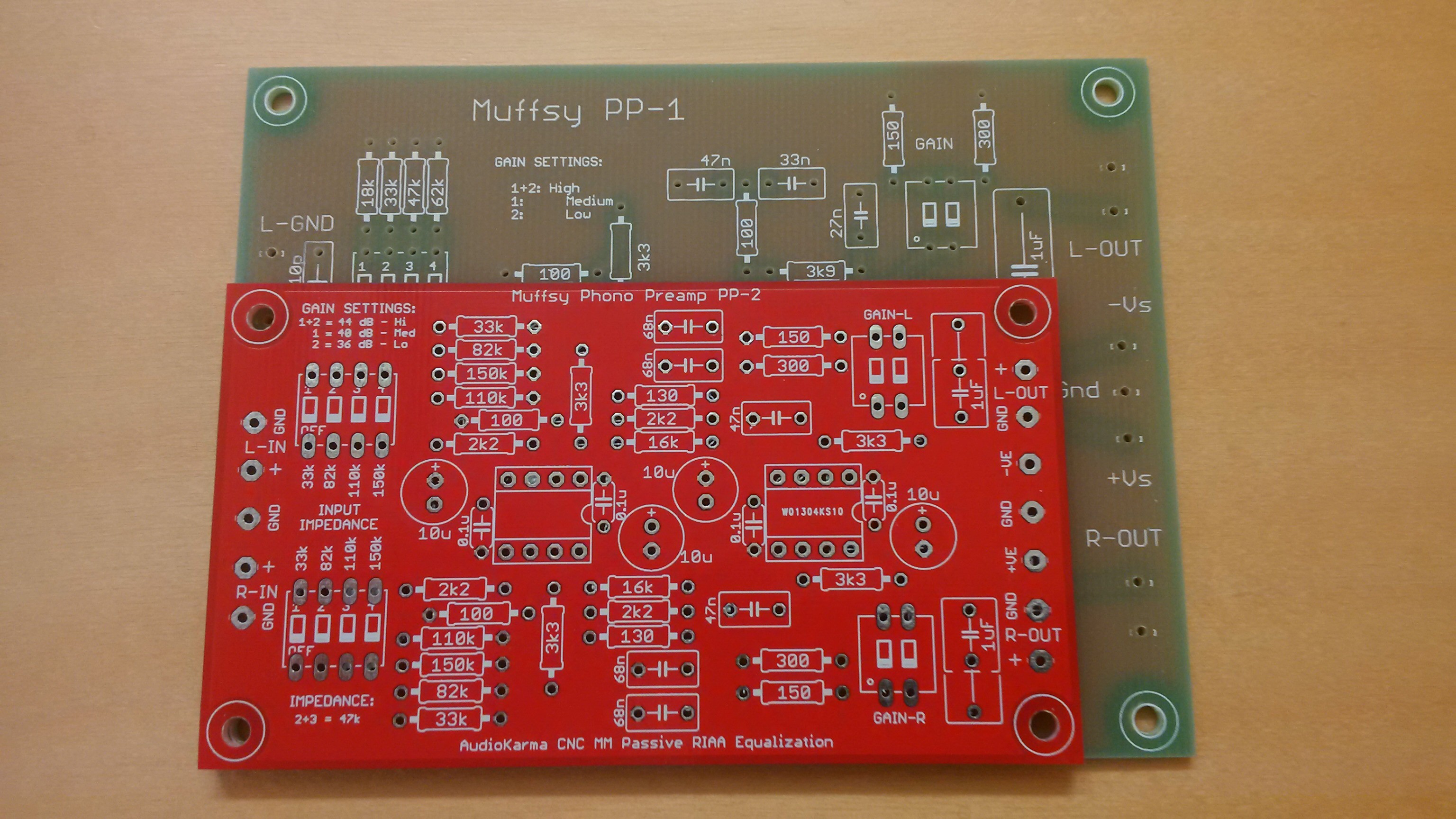
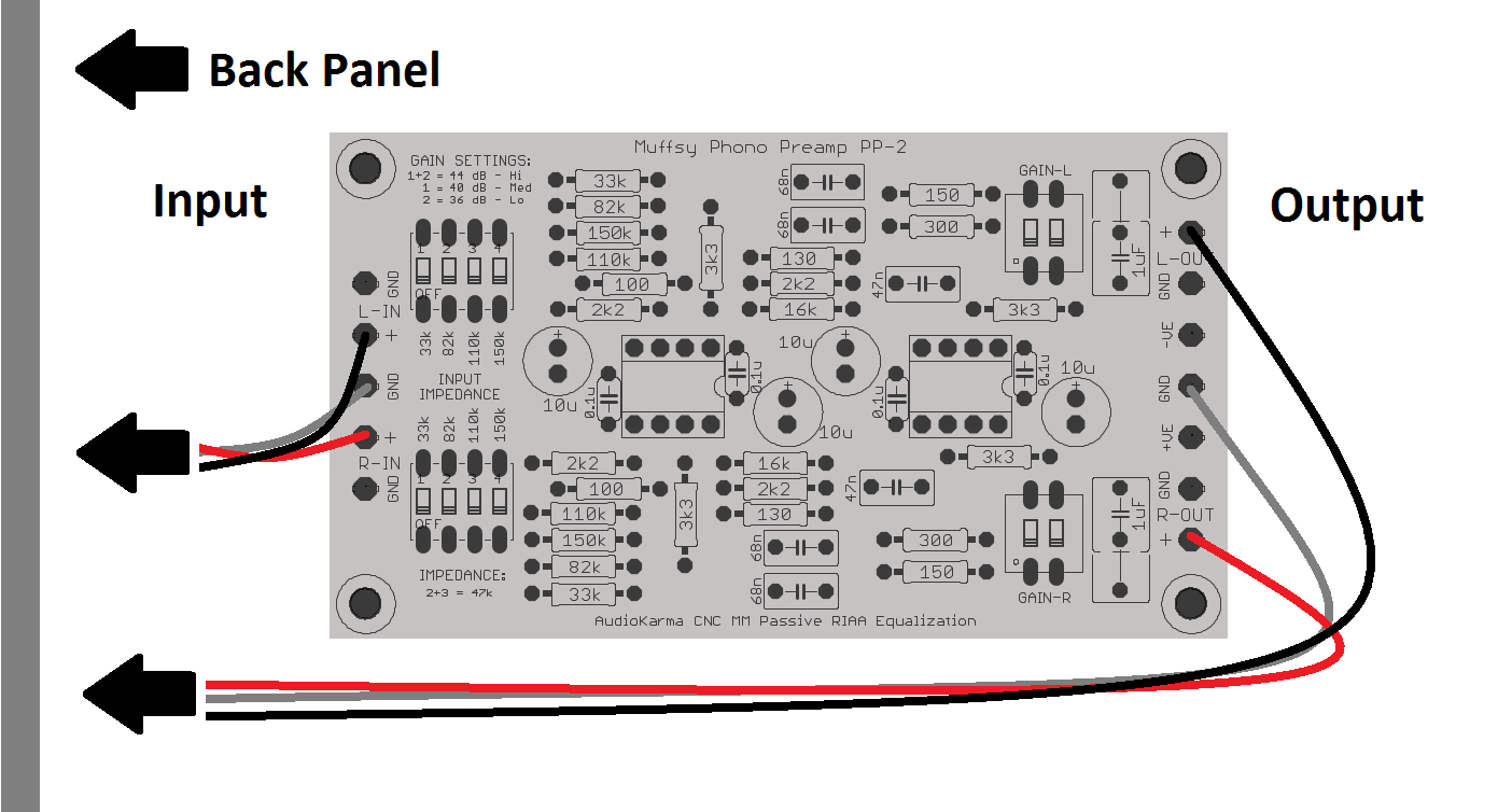
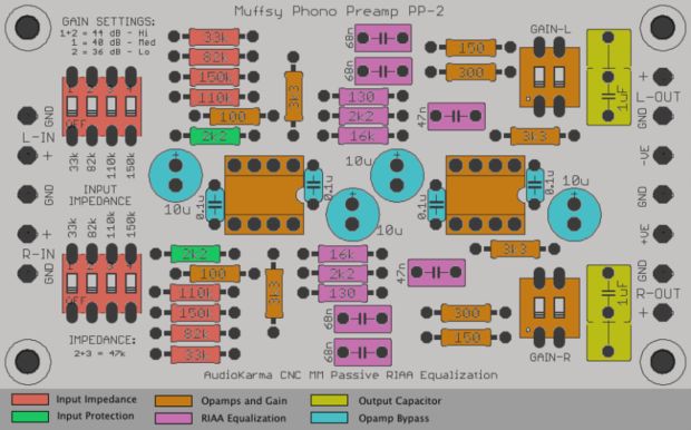
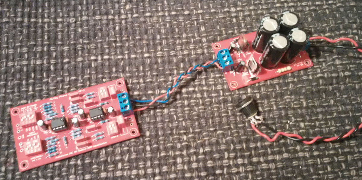
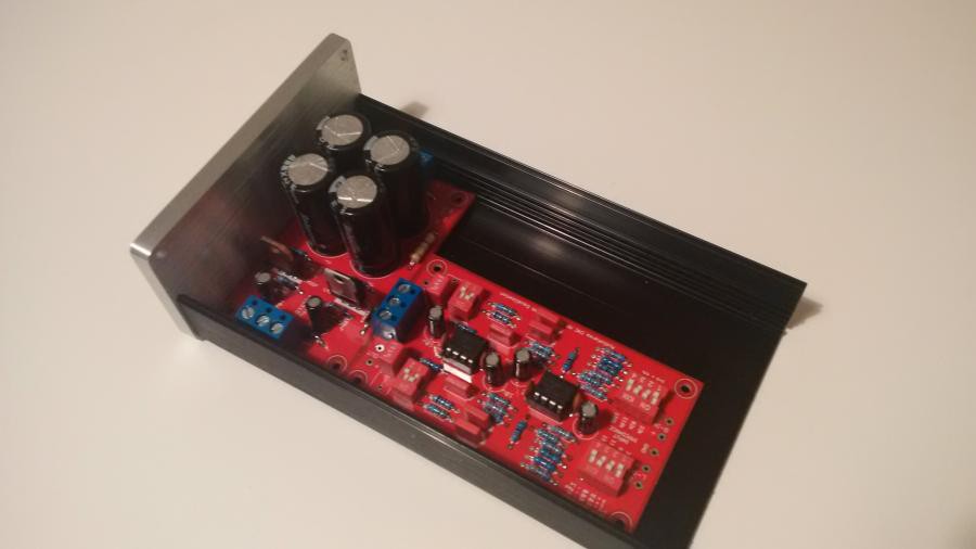
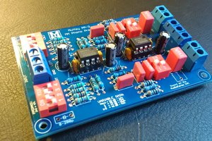
The Muffsy Phono Preamp PP-2 has improved upon this circuit:
- The PCB is 40% smaller than the original size
- The PCB is dual layer with a full ground plane
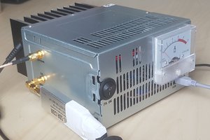
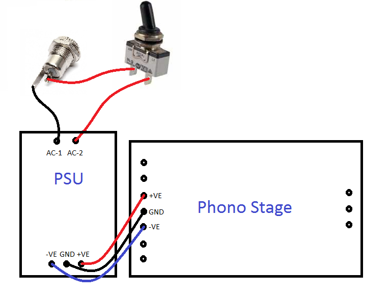
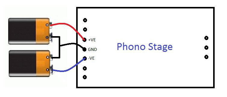
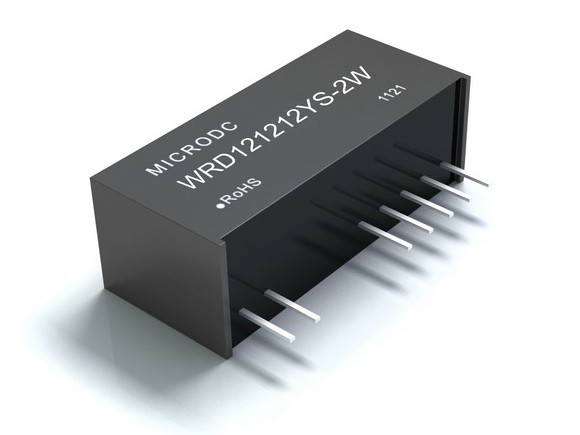
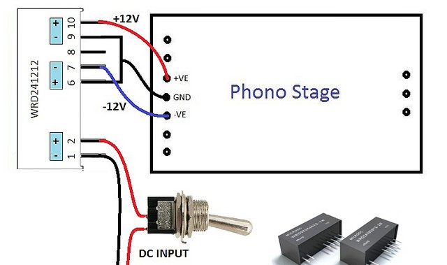
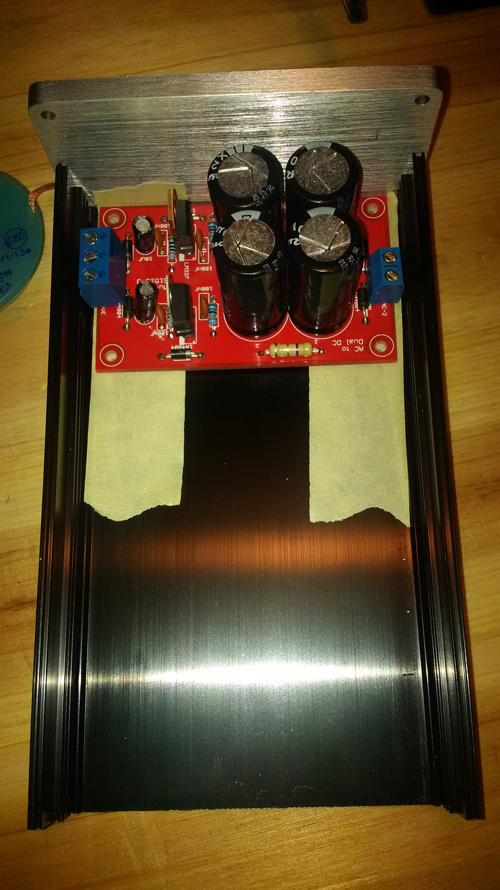
- It's got a high quality companion power supply
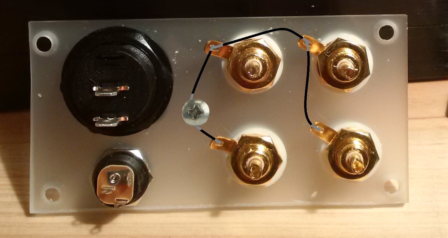
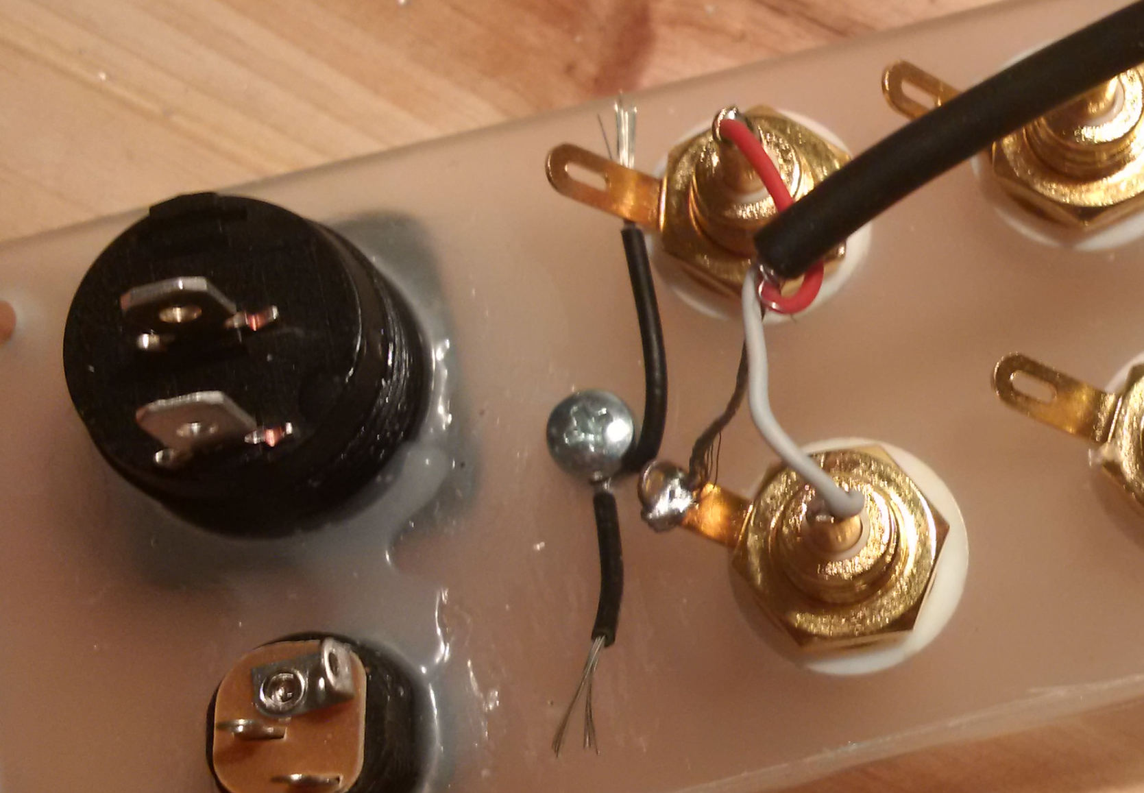
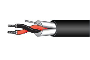
- Easy connection of two-lead shielded audio cable
- The input capacitor is removed
- Input impedances are much more useful
- Variable gain, 36/40/44 dB @ 1 kHz
- Redesigned RIAA filter
- The board uses only standard component values
- Terminal blocks can be used on the input/output/power connections
- Detailed documentation and build instructions at Instructables
- Even more interesting information in the hackaday.io Project Log
- It's red!
- You can even etch your own PCB

 ElectroBoy
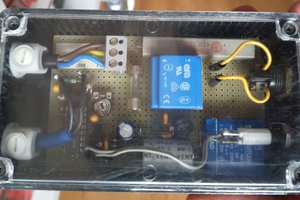
 Entunassa