Close
0%
0%

Propeller Based CNC Router Controller

A relatively simple controller for my CNC router using a Propeller Microcontroller.

Similar projects worth following
I plan to build and program a device to provide step and direction input to my CNC router.
The CNC router will be used to cut parts for my Health Maintenance Robot I plan to build as part of the 2015 Hackaday Prize contest.

This CNC router will be used to cut parts for my Health Maintenance Robot I'm building as part of the 2015 Hackaday Prize (there wasn't an option to add this link in the description).

The controller has two Propeller microcontrollers. One Propeller acts as a graphics slave (and keypad reader). The other Propeller will generate the direction and step pulses to drive the stepper motors.

While I may eventually purchase a PC and software to use a "proper" controller, I want to try controlling the CNC router with a Propeller microcontroller first.

I'm hoping the controller will be able to read a SD card which will contain the desired tool paths. I would also like to be able to manually control the router with the attached 16 button keypad.

While most of this project will consist of programming the controller, I also need to finish putting together the CNC router.

I haven't taken photos of the router yet but I will likely do so within the next few days.

  • Circular Motion?

    Duane Degn05/28/2015 at 03:26 0 comments

    I wrote some code to produce (what I hope is) circular motion. I haven't connected the stepper motors to the CNC router yet but the movement of the motors looks like it should produce circular motion on the x, y bed.

    I think the video is just about as boring as they come (with the exception of a few unboxing videos) but I wanted to share it since it was so darn difficult to program.

    The program is written in assembly and uses integer math for all the calculations.

    The stepper motors accelerate to their full speed but I didn't include a deceleration section of code (yet).

    The program "TestMotorsPasmCircular.spin" is the top object used in this demo. The code is located in my GitHub "CncController" repository. This repository is presently very unorganized. So far I've been working on individual pieces of the overall program. I still have a lot of work combining these pieces together.

  • Mini Update, Dual Stepper Control

    Duane Degn05/03/2015 at 18:14 0 comments

    I wrote some assembly code to accelerate and decelerate two stepper motors. The acceleration profiles of both motors should be such as to produce linear motion (at least I think it will).

    My code is now available from my GitHub account under "CncController."

    The "TestMotor" object is the object I used to test the motor control algorithm.

  • Different Hardware

    Duane Degn04/26/2015 at 07:59 0 comments

    I couldn't get the original stepper driver to work even when using level shifters to convert the 3.3V logic to 5V logic.

    Someone on the Parallax forum mentioned the DRV8711 stepper driver so I decided to give the DRV8711 a try.

    I knew programming the CNC controller wouldn't be simple but dang it, it's downright hard. I find myself taking detours as I write the program. I think "wouldn't it be nice if I could display bitmaps as well as text on the OLED screen?" So I add a way to insert a bitmap into the display buffer. (I've tried to do this in the past and failed. This time I succeeded. ) Then I think "wouldn't it be nice if the dark areas of the bitmap could be transparent?" So I add a way to OR the two images. (IMO this looks pretty cool.) I also added code to invert a section of the bitmap. I'll likely inverted a line of text as a way to indicate it has been selected.

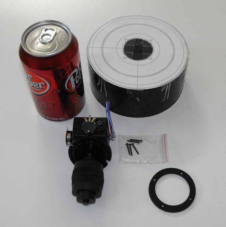
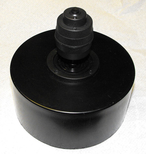
    Another sidetrack was making a mount for a joystick I saw in a Hackaday article. I then needed to incorporate the joystick into the CNC interface.

    Here are a couple of pictures of the joystick. This first one shows the PVC cap I used prior to cutting the holes. I added the Dr. Pepper can to provide scale.

    This next photo shows the joystick mounted to the PVC cap.

    I confess to not really needing another joystick, but I thought this one looked really cool. Here's a link to the Aliexpress seller.

    I made a video showing the OLED displaying both text and graphics. The video also shows how I was able to invert a section of the screen.

    Since I'm not using the original stepper driver hardware, I decided to switch the rest of the electronics hardware too. I'm using a different Propeller control board and a different display than I previous used for this project. This current configuration of hardware is easier to modify than my previous hardware.

    The NTSC video display I previously used required my using a second Propeller chip as a graphics slave. The smaller OLED display can be driven from same Propeller chip as the one I'm using to control the stepper motors so I'm now just using one Propeller microcontroller.

  • The Main Hardware

    Duane Degn03/16/2015 at 23:00 0 comments

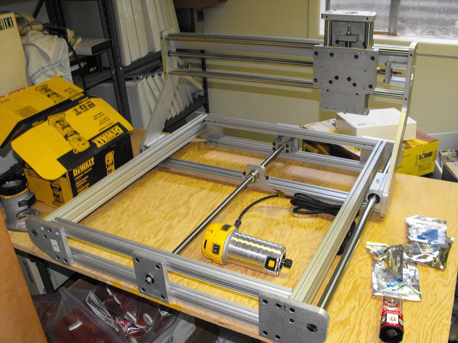
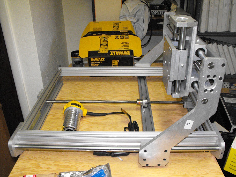
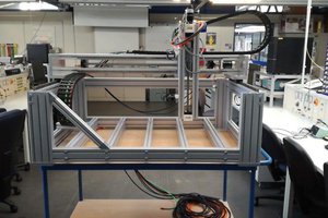
    I took a couple of photos of the CNC frame.

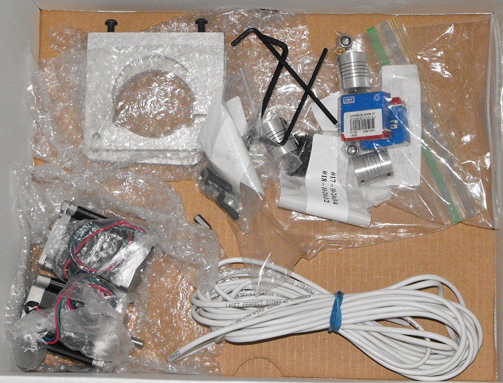
    Besides the electronics I earlier photographed, there are also some other parts in shown in the above photos. These include the router mount, stepper motors and other miscellaneous parts.

    I'm using the third stepper motor to test the electronics so it's not included in the box of parts photo.

    There's also a piece of heavy plywood which will provide the base of the work area. A piece of sacrificial MDF will be on top of the plywood.

    While the overall frame has been built, I haven't tightened all the bolts yet. I want to be able to move the components as I tighten everything in place to make sure there isn't any binding.

    I've had these parts for over a year. I'm excited about the prospect of finally getting this thing up and running. IMO, it's a pretty nice machine and it's a shame to have it sitting idle.

  • 3.3V Logic Isn't Enough

    Duane Degn03/16/2015 at 04:17 0 comments

    I began work on this project again today after having set it aside for about a year.

    My first attempt to drive a stepper motor wasn't successful. After checking the wiring to make sure the signals from the Propeller were reaching the drive electronics, I then monitored the signal while the program was running but without connecting the Propeller to the drive electronics. While disconnected, the step signals from the Propeller were a nice 0V to 3.3V pulse. When the signal was connected to the drive electronics I found the signal line no longer produced a nice consistent pulse. I'm pretty sure the optocouplers can't be driven with a 3.3V signal.

    I'll need to use some sort of level shifter to boost the 3.3V signal from the Propeller to a 5V output the drive electronics can use.

View all 5 project logs

Enjoy this project?

Share

Discussions

Matthew Gingerich wrote 11/20/2015 at 02:46 point

I did the same project a few years ago. I had one propeller controlling a big XY table I made. My code would draw images based on text input of points, which was kind of cumbersome. Are you by any chance using different cogs to control the X and Y motors simultaneously? I tried to get that to work to see if I could get smoother movements, but I had trouble synchronizing them, so I ended up implementing the motor control in a single cog.

  Are you sure? yes | no

Duane Degn wrote 11/24/2015 at 04:28 point

The motor control is done in a single cog.

I think I can get straight lines and circles but my circles have to start at 1/8 circle intervals so far. 

I've found the acceleration aspect of the code very challenging.

My code it very cumbersome. The code it too large to fit in RAM all at once. I have load various sections of the code from the SD card as those sections of the program are needed.

  Are you sure? yes | no

Matthew Gingerich wrote 11/24/2015 at 17:36 point

I sort of had the opposite of your problems with my code. I can easily and smoothly draw circles, lines, and other shapes, but when I wrote it I lacked the skill to make it do toolpath planning or graphics processing or reading from and SD card. The most advanced thing I got to work was just drawing homer simpson from a list of coordinates. Maybe we could share code with each other? My motor control algorithms are probably a lot different from your needs though, because I built the stepper drivers from scratch. I dedicate 4 I/O pins to each stepper and use them to pulse the coils in sequence. 

  Are you sure? yes | no

EncoreTech wrote 03/17/2015 at 00:24 point

Is the frame a kit, or your own design? I would love to see more detail about this project as it nears completion.

  Are you sure? yes | no

Duane Degn wrote 03/17/2015 at 02:21 point

I purchased the frame, motors and motor drivers as a kit on ebay. I believe this is the same kit:

http://www.ebay.com/itm/261808900783

When I purchased it, it cost just under $1,500 shipped. This was a very significant purchase and I feel silly for not having it up and running yet.

  Are you sure? yes | no

Similar Projects

Does this project spark your interest?

Become a member to follow this project and never miss any updates