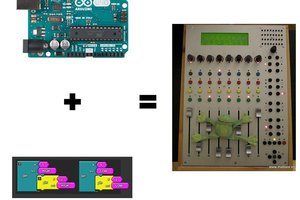
• It lives!

    Karl Bielefeldt03/23/2015 at 20:35 0 comments

    The previous project logs were all written in retrospect. With this one, I'll be caught up to the present.

    Board bring up was fairly uneventful, just a ton of soldering. It all came up on the first try, and I did not need to add any buffering. My Arduino Uno clocked all 14 shift registers at once, no problem. The only big issue was not my fault. The 45 year-old original board I'm interfacing with had one broken tab:

    I didn't really fix it properly, just soldered some hookup wire and wadded it up to jam into the connector. I don't expect to be unplugging it very often.

    Partially, progress has been a little slow, because it's just too fun to play, even with partial functionality! I'll post a video after I get the volume pedal working.

    I also have a DPDT switch near the lower manual that was originally part of the accompaniment functionality. I'm not sure exactly what it did because it didn't work when I got it. I'm thinking of making that switch some sort of preset button, or emulate a third keyboard, or shift the upper manual up and down an octave. Let me know if you have any other ideas in the comments.

  • Circuit Board

    Karl Bielefeldt03/19/2015 at 00:10 0 comments

    OSHPark.com has great prices and quality for hobbyist-sized runs of circuit boards, but you get three copies, so I want to take that into account in the design. In this case, I have three keyboards, so there's a natural division. That means six shift registers per board, 48 notes each, leaving a few spares. My pedalboard only has 13 keys, so I need a way to partially populate the board. Also, with 14 shift registers, we have a potential for wanting some buffering, so I want to make space for that on the board, but also create a way to leave it off if it turns out not to be needed. End result is here.

    The ordering of the inputs to the shift registers looks odd, but it makes the routing much simpler, and is easy to arrange in the software. The boards look like this:

  • Making Sound

    Karl Bielefeldt03/17/2015 at 16:43 0 comments

    Who can design a circuit board when you have a prototype sitting on your desk and just need a little software work to make some sound? Not me! I took a small detour in order to be able to get a small taste of the end product.

    I am primarily a church organist, so I mostly wanted a pipe organ sound, although certainly I may hook up a jazz organ synth every now and then. You can get virtual pipe organ software that receives midi messages and plays audio samples recorded from real organs. The big name in this field is Hauptwerk, but I wanted my project to be open source and run on Linux, so I chose GrandOrgue, which is very nice.

    Next problem is Arduinos look like a serial port when you want them to look like a midi device. There is a hiduino project to do this over USB without any drivers on the computer side, but that was more modifications to my Arduino than I was willing to do at the moment, so I used Hairless MIDI serial instead. It has a weird name, but works very well for converting serial port messages to a midi device, and has a nice debug output as well, which is perfect for this sort of project. I will probably do the hiduino solution eventually, but only after my firmware has stabilized.

    So a little work on my Arduino sketch, and nice pipe organ sound for 22 notes! I will post my code and other design files to github later. The biggest gotcha was even though I was sending a note off event, it still expected a velocity of zero, or GrandOrgue wouldn't actually turn off the note. Hairless' debug output was perfect for troubleshooting this. I could see that my messages were being received correctly, which eliminated many potential sources of error. Also, GrandOrgue being open source helped tremendously, because I could actually look at the code that was processing the note off events.

    Now on to designing a full schematic, for real!

  • Initial Design

    Karl Bielefeldt03/17/2015 at 16:08 0 comments

    Note: I'm nearly done with the first phase of this project, but I wanted to document each step in retrospect. I'll let you know when the project logs get caught up to real time. This site is a great resource. My next project I will document as I go.

    Several years ago, I received a Hammond spinet organ for free from an acquaintance at church. It was built in the 60s or 70s, but even when it was new, it was one of the cheapest models in their cheapest line. It had several issues with notes or stops that wouldn't play, or worse, would play incorrectly. It sounded terrible, and I have no nostalgia for such things, but I wanted something I could practice on that sounded nice. After seeing some other midification projects, I decided to do my own, and ripped out all the guts and threw them out.

    The first thing I needed was a way to read all 101 keys, with n-key rollover. The keys had a separate wire for each key, no multiplexing at all. My first thought was to just wire them straight into 3 microcontrollers, but when I started the schematic design, I realized that solution wouldn't be as simple as I thought. The microcontrollers I wanted to use only had pullup resistors on some of the IO pins, so I would have to add my own anyway for the vast majority of the keys. I also didn't want to have to worry about maintaining firmware on three separate devices and how to implement chip-to-chip communication.

    What I ended up going with is plain old parallel-to-serial shift registers going into the SPI port of an arduino at the end. This meant one microcontroller to program, but I didn't need to worry about its wiring. I would already have USB power available, and it would be easy to incrementally implement. I could order three identical boards from OSHPark, and could use the same boards later to expand if I so needed, such as to add stops or preset buttons.

    I ordered parts and breadboarded a prototype, and my circuit worked perfectly the first time. The simplicity of the design was really beneficial. Only three signal wires needed into the Arduino: load/shift*, SPI clock, and MISO. First version of software just wrote the hex bytes out to the serial port.

    This prototype also helped definitively answer a question I had about software debouncing after a shift register. I needed to know if I needed to add some sort of schmitt trigger or other circuit before the original input. Turns out, I had no cause for concern. Debouncing worked perfectly with a straight connection to the shift register input. On to full schematic design!