 Karl Bielefeldt
Note: I'm nearly done with the first phase of this project, but I wanted to document each step in retrospect. I'll let you know when the project logs get caught up to real time. This site is a great resource. My next project I will document as I go.
Several years ago, I received a Hammond spinet organ for free from an acquaintance at church. It was built in the 60s or 70s, but even when it was new, it was one of the cheapest models in their cheapest line. It had several issues with notes or stops that wouldn't play, or worse, would play incorrectly. It sounded terrible, and I have no nostalgia for such things, but I wanted something I could practice on that sounded nice. After seeing some other midification projects, I decided to do my own, and ripped out all the guts and threw them out.
The first thing I needed was a way to read all 101 keys, with n-key rollover. The keys had a separate wire for each key, no multiplexing at all. My first thought was to just wire them straight into 3 microcontrollers, but when I started the schematic design, I realized that solution wouldn't be as simple as I thought. The microcontrollers I wanted to use only had pullup resistors on some of the IO pins, so I would have to add my own anyway for the vast majority of the keys. I also didn't want to have to worry about maintaining firmware on three separate devices and how to implement chip-to-chip communication.
What I ended up going with is plain old parallel-to-serial shift registers going into the SPI port of an arduino at the end. This meant one microcontroller to program, but I didn't need to worry about its wiring. I would already have USB power available, and it would be easy to incrementally implement. I could order three identical boards from OSHPark, and could use the same boards later to expand if I so needed, such as to add stops or preset buttons.
I ordered parts and breadboarded a prototype, and my circuit worked perfectly the first time. The simplicity of the design was really beneficial. Only three signal wires needed into the Arduino: load/shift*, SPI clock, and MISO. First version of software just wrote the hex bytes out to the serial port.
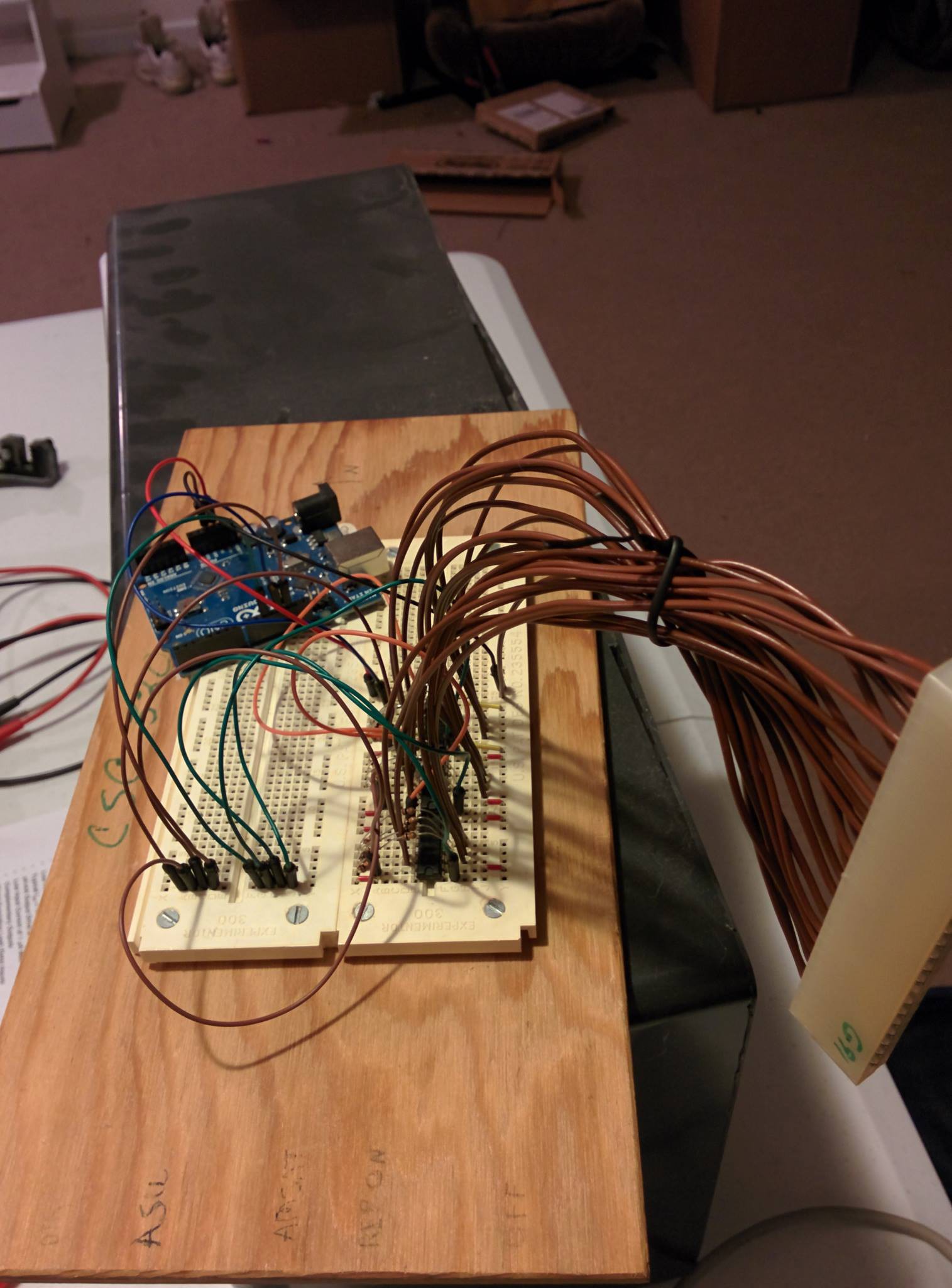
This prototype also helped definitively answer a question I had about software debouncing after a shift register. I needed to know if I needed to add some sort of schmitt trigger or other circuit before the original input. Turns out, I had no cause for concern. Debouncing worked perfectly with a straight connection to the shift register input. On to full schematic design!
Discussions
Become a Hackaday.io Member
Create an account to leave a comment. Already have an account? Log In.