Close
0%
0%

PIC32 Espresso Machine Controller

Using a PIC32 to control brew pressure, steam pressure, and extraction time on a heat exchanger style espresso machine.

Similar projects worth following
The project is to replace the old mechanical pressurestat in an espresso machine with a solid state relay, a pressure transducer and a microcontroller to obtain more tightly controlled temperature in the heat exchanger and therefore get more consistent results. In addition, the microcontroller will operate the pump when the brew switch is turned on, allowing for programmable extraction timing, and automatic pre-infusion, and accurate programmable brew pressure. The controller will output the temperature and pressure parameters of extraction so that we can do experiments on the effects of these parameters on the output, measured in deliciousness of the espresso (and possibly pH).

In making good espresso, consistency is of the utmost importance. The key factors affecting the taste of espresso are temperature, tamping pressure and technique, brew pressure, extraction time, and of course the beans you use. The problem of consistency is difficult to solve with old technology found in most machines because the tolerances are often relatively wide. For example, one shot to the next might taste different but it's hard to say whether or not the shot was pulled at a higher temperature due to the huge deadband on the pressurestat, or the brew pressure was a little higher, or if it was due to human error such as packing the beans too tight. Most people end up assuming the latter, and adjust their (potentially fine) technique, which obviously isn't going to solve the problem.


There are a couple variables that affect the outcome which depend on the technique of a human (such as tamping the beans), which can't be precisely replicated time after time. A perfect example of this is tamping technique. It's very hard to measure, and it's not easy or fun to build a machine that tamps for you.

There are, however, many variables that can easily be controlled by a microcontroller for more repeatable results.

  1. We can more tightly control the steam pressure of the heat exchanger so that water passing through en route to the brew group head is a more consistent temperature every time.
  2. Water sitting in the heat exchanger for a long time between shots tends to get hot, which leads to an inconsistent temperature. If the heat exchanger pressure is set so that fresh cold water coming through the heat exchanger is the perfect temperature upon exit, then water that sits idle inside the heat exchanger for an extended period of time is going to be too hot. To mitigate this problem we can add logic to automatically flush the heat exchanger until the right temperature is reached to ensure consistent temperature every time.
  3. We can control the pressure of the water coming through the shower head.
  4. We can control the length of time the water flows through the shower head. Pulling shots for too short or too long leads to bitter or sour tasting espresso. Normally, baristas observe the color and opacity of the liquid coming out to determine when to cut off the pump. When the espresso becomes light in color and a little more transparent, this is called "blonding", and is a sign that it's time to stop. It would be interesting to attach a color sensor and attempt to have the microcontroller shut off the brew switch at the moment blonding is observed.
  5. We can allow a small amount of low pressure water sprinkle on top of the beans and settle before the full pressure water is pulled through. This is called pre-infusion, and can manually be done by pulsing the pump button a few times, waiting a couple of seconds and then leaving it on to actually pull the shot. It would be much nicer and more consistent if this were done automatically via the microcontroller.

In addition to precise control, I'd like the parameters to be easily adjustable so that we can fine tune, and also have presets for different roasts and different grinds. I plan to have the temperature and pressure readings output as a graph on the display during the brew cycle so as to monitor the stability of the system. Typically when people have plotted brew temperature over the length of a 30 second shot, you can observe a temperature drop of a few degrees, and it would be interesting to see what could be done to make this as constant as possible.

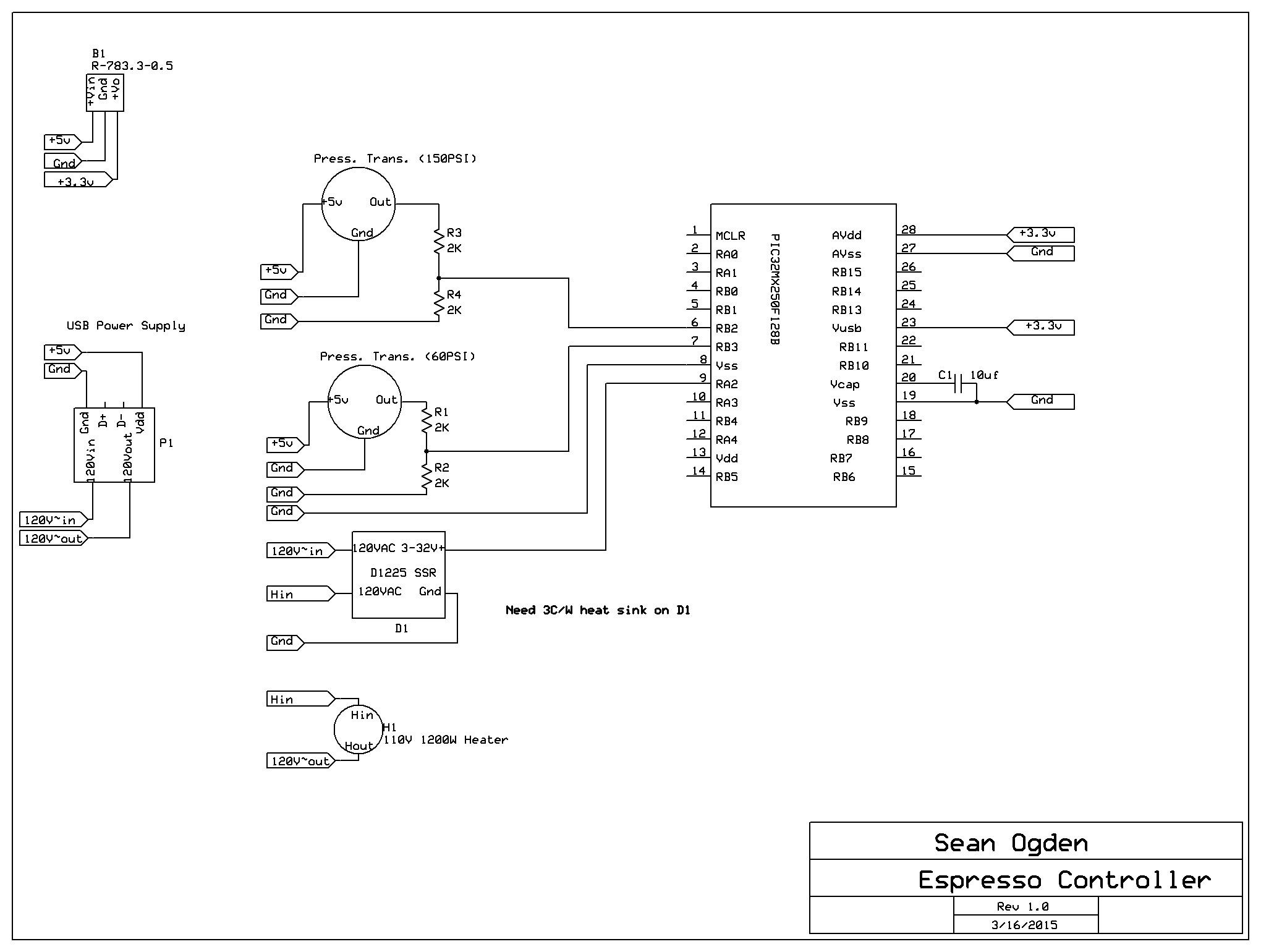
I thought about having a basic LCD with a few buttons, but ultimately I was drawn to the simplicity and compactness of a touch screen TFT. You can see details about making the TFT work with PIC32 in my PIC32 TFT driver project.

  • Designing the circuits

    Sean Ogden03/17/2015 at 19:00 0 comments

    My end goal is to print a circuit board in order to make the project compact enough to fit within the case of the machine. I've never done that before and I'd like not to screw it up, so I'm drawing the schematic out so I can think about it and verify that it's correct.

    I started designing the circuit for the controller today. The basic components of the machine are the vibration pump and the heater. Both use 120VAC, so I'll need to use two solid state relays in order to control them with the PIC32.

    At this time, I've designed the circuit to measure two 5V pressure transducers and switch one SSR to control the heating element. I have yet to design for the brew control, or the screen but that will be done later.

    Power supply

    I will be using a USB charger as the power supply, directly wired to the 120V coming from the wall. This was easier and safer than trying to design my own power supply (I'm not an EE), and it supplies the 5V I need to run the sensors. I also need 3.3V to run the PIC32, so I've used a dc-dc step-down converter to supply that voltage from the 5V supply. All of the Vdd and Vss pins on the PIC32 are connected to the 3.3V and Ground. In addition, I have the 10uf capacitor connected to Vcap and to ground, as per the following instructions on the datasheet "The Vcap pin must not be connected to Vdd, and must have a Cefc capacitor with at least 6V rating connected to ground". The capacitor can be either ceramic or tantalum.

    Reading 5V sensors on the 3.3V PIC32

    In order to read the 5V sensors from the PIC32, I needed to divide the voltage to something lower than 3.3V. For this, I've used a voltage divider with 2 2k ohm resistors on each sensor, so the output voltage is 5V*(R2/(R1+R2)) = 0-2.5V.

    Switching 120VAC heating element with 3.3VDC PIC32

    For switching on and off the heating element, I had planned on using a 10A 120VAC SSR. However, the heating element being 1200W 110V means that I need something at least 11A. So instead I'm using a 40A 120VAC SSR that I found on a surplus site. It does not have a datasheet, so I'm just going to have to try and see if it needs a heat sink.

  • Reassembly

    Sean Ogden03/17/2015 at 18:34 0 comments

    Now that the machine is completely clean, I had to reassemble it. Thankfully, I took a LOT of photos. It's a simple device, but many of the copper pipes look quite similar and are not the same. I forgot to take a photo of the whole thing back together, but here's most of it. I'm going to clean up the case at a later date and probably paint it, but at this time it was -20 degrees F outside, and so paint would likely not dry. So for now I'm just making sure everything works. Surprise, it does work. The steam pressure on this thing is impressive.

  • Cleaning up

    Sean Ogden03/17/2015 at 18:29 0 comments

    The first step was to clean up the components. This machine had been sitting with water in it for quite a while. There was a lot of scale buildup that needed to be cleaned up before I was going to taste anything that came out of it. So, I disassembled the whole machine and put all of the parts in a bath of hot Citric acid for several hours.

    It came out very clean. You can see at the bottom of the heat exchanger where the fitting has become detached due to a failed weld. This was the culprit of the leak, and was easy enough to repair myself without having to buy any parts.

  • Humble beginnings

    Sean Ogden03/17/2015 at 18:24 0 comments

    The project started as a way for me to learn how an espresso machine works, and also taste some good coffee. Espresso machines that are worthwhile tend to be quite expensive. However, as with many high end kitchen appliances, it's not a very complicated machine. In fact, it's mostly a pile of copper pipes, a heater and a pump. The entire thing is controlled by mechanical switches and every component is 120VAC so there's not a diode in the entire thing.

    This is good news because it means that if you can wire a switch, and braze copper pipe, you can probably fix an old espresso machine, and even if its discontinued you can make new parts with standard plumbing fittings and basic electronic components.

    I purchased my machine on eBay very cheaply. As in scrap metal cheap. It's an old machine and the owner didn't really know how it worked, and it was leaking from the heat exchanger. Unfortunately they don't sell that heat exchanger anymore. The machine is a Mini Wega from the 1990s (very similar to, but not to be confused with the Wega Mininova). A used one in good condition is about $2,000 last I checked, so it was a worthwhile project to see if I could get it working again. Here's a photo of what it looked like.

View all 4 project logs

Enjoy this project?

Share

Discussions

Similar Projects

Does this project spark your interest?

Become a member to follow this project and never miss any updates