 Luc
LucOverview:
I was inspired to build my own electronic compass after seeing the compass demo on the STM32F3 Discovery board and there have been a few times recently when I was navigating a new city or area, and had wished that I had brought a compass with me. This project will be to develop an electronic compass similar to the demo on the discovery board, but much more portable than lugging around a full development board and 5V supply. I'm hoping that setting up this project will motivate me to document my progress all the way through, and hopefully there are some other people who would be interested in building one of their own (provided I actually get this done in a reasonable amount of time).


 Benjamin Broce
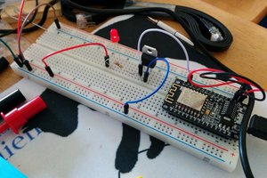
 WJCarpenter
 blinkingthing
 Corey Benn
Just a friendly reminder to please upload your design documents by 23:59 UTC on Dec 8, 2015 to be in the running for #The Square Inch Project!