 ajlitt
I spent some quality time in KiCAD finishing TBD v0.2 over the last couple of weeks. I ordered boards, stencils, and parts which should take a couple of weeks to trickle in. Files in the Github link to the left. Here are the deltas from v0.1:
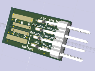
- Surface mount 2x4 header mounted on the backside to reduce overall length
- Rethought pinout brings out 6 pins that can be muxed between I2C, SPI, FlexIO (general purpose serial engine), and ADC
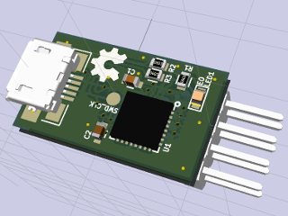
- Option to use a micro USB jack instead of the USB-A board edge. Fits to the back side of the USB-A pads.
- BOOT pin placed next to GND so a 2 pin jumper can be used to force ROM boot mode
- 0603 discretes for easier manual placement and less risk of tombstoning
- Resistor in line with the LED
- SWD_CLK moved to test pad to save 1 pin on the header. SWD_IO is shared with one of the I2C pins
- Silk legends for pin GPIO names and main alternate function
I also had some time to play with using a web browser to talk to the bootloader via HID. I started with the Sparkfun Firefox HID example
as a base and ended up with a simple page that's able to reset the part
and read memory as a proof-of-concept. Now that the board is in
production, I can spend some more time on this part of the project.
Discussions
Become a Hackaday.io Member
Create an account to leave a comment. Already have an account? Log In.
Hi,
Adding the uUSB jack pads on the back side of the USB-A will not cause a sort circuit when you plug in the board without populated uUSB into USB-A? Or you plan to cover this pads somehow?
SUF
Are you sure? yes | no
There will be a plastic shim stuck over the microUSB pads to improve fit in a USB port. I found this was necessary on v0.1 for reliable contact with the port. On boards with the microUSB connector the shim will be stuck over the USB-A pads.
On my to-do list is to find a more manufacturable solution. Right now the shims are cut from discarded blister packs and glued with CA.
Are you sure? yes | no
Also, when you say easier placement with 0603, did you mean in the soldering process? Because I would have thought 0402 like you used before would be easier for PCB layout.
Are you sure? yes | no
By "placement" I meant physically placing parts before reflow. Getting the 0402 parts on the board was tedious even with tweezers and a magnifying glass, and they're more prone to tombstoning than 0603. I edited the post to clear this up.
Are you sure? yes | no
Thanks for the replies!
I'll be getting a frdm-mkl27z dev board, can you point at resources for using the ROM bootloader?
Are you sure? yes | no
Freescale has a product page dedicated to the bootloader: http://www.freescale.com/webapp/sps/site/prod_summary.jsp?code=KBOOT . The "downloads" tab has the binaries and source for a couple of Windows applications to flash the part. I haven't been able to get the GUI one to work, but the CLI "blhost" works with my boards.
I didn't know that there was a FRDM-KL27Z. Sadly it's not directly compatible with the part I'm using on TBD. Freescale uses obtuse marketing names for their parts, with some chips in different families sharing the same die and some in the same family being completely different internally. The part on this FRDM board is not compatible with the 128k and 256k KL27 I'm basing the TBD on. The MKL27Z256VFM4 is a pin-reduced MKL43Z, while the 32k and 64k MKL27Z parts are an altogether different chip. That shouldn't matter if you intend to use KDS, but for mbed the offline KL43 target I'm using with my board will not work with this part.
If you spin your own board that relies on the ROM bootloader, be careful that the FTFA_FOPT word in any image you flash allows ROM boot to run. Otherwise you'll need an external debugger to reflash it. Both mbed and the KPSDK targets for KL43 set this so that ROM boot isn't run regardless of the BOOT pin state.
Are you sure? yes | no
Thanks, I must have missed that somehow! Shame it's Windows only.
Wow... I didn't know that, that's super annoying.
The part I'm currently using is MKL26Z256VLH4, and I wanted to move to the MKL27Z because of the crystal-less USB and the ROM bootloader. Do you know if the MKL26Z256VLH4 is more like the 128/256k MKL27 or the 32/64k MKL27? How did you find out that it was just a cut down MKL43?
Depending on the bootloader, I might use my own DFU bootloader anyway, but I think it's good to keep the ROM one also accessible!
Thanks for the help!
Are you sure? yes | no
There are a few ways I've found to tell the relationships between Kinetis parts, none of them obvious. One is to look at the "parametrics" parts list for the related eval board. They tend to have one FRDM board to represent all Kinetis parts that share the same silicon. So if you look at MKL27Z256VFM4 it shows FRDM-KL43Z. You'll also notice that the MKL26Z256VLH4 uses the FRDM-KL46Z, while the KL26 parts with less flash use the FRDM-KL26Z.
Another is to look at the first couple of pages of the datasheet for the "Chip Errata" document. The errata are organized by the "mask set" name, and the name of the errata document ends with the mask set. In the case of the KL27 I'm using, the mask is 1N71K, which you'll find in the datasheet for the KL43Z as well.
Finally you can diff the headers in the SDK for each chip. In KSDK the headers seem to be autogenerated such that there are unique headers for each variant in a family. So if you diff MKL27Z4.h and MKL43Z4.h, you'll notice that the files are roughly identical except for the LCD registers that are only in the MKL43Z.
The MKL26Z256 is very similar to the MKL27Z256. The KL27 adds the boot ROM, crystal-less USB, FlexIO, and ADC VREF, but it does not have the touch sense that the KL26 has.
Are you sure? yes | no
Thanks, useful info.
I went here http://www.freescale.com/webapp/sps/site/prod_summary.jsp?code=FRDM-KL26Z and it says: "For development tools for KL16 and KL26 with 256 KB Flash or greater than 64-pin packages, please use FRDM-KL46Z and TWR-KL46Z48M."
However the reference manual for the KL26 mentions support for the MKL26Z128 and the MKL26Z256. I've been developing on the FRDM-KL26Z but bought the MKL26Z256 chips (they were only 0.01p more expensive, so I thought I might as well!) So I hope everything will work as-is!
How long until you get the rev2 boards? I'm interested in buying one.. or maybe rev3 or 4 :P
What hot air station are you using?
Are you sure? yes | no
Thanks for the info. I'll be using using MKL16 and the accelerometer (same as one in the freedom board ) for my project. :)
Are you sure? yes | no
You're right about the differences. Now that I look, the KL26 series is extra confusing since the 128K variant in QFP-100 is a different mask set from the 128K in QFP-64, but is the same mask as the 256K in QFP-64. I'd be mad if I designed a board expecting to easily scale up or down memory with a BOM change.
Rev 2 parts and the stencil should be in my mailbox right now, but boards will be a couple of weeks. You probably are better off waiting for the next rev.
For reflow, I'm using a butane hot air pencil from the hardware store and a thermocouple to monitor the surface temp. See the pics. Because this board is small I can get away with this. It's time consuming and uses a full charge of butane per board, so I'm considering building a reflow toaster if I end up doing another batch of these.
Are you sure? yes | no
I used a butane torch too with very good results for QFN parts! Now I am trying to buy a hot air reflow tool as butane are getting expensive. BTW I am using the $20 Beck & Decker toaster oven - works well. I made some modification to the thermostat to allow for slightly higher temperature.
Are you sure? yes | no
This is all mighty confusing by Freescale.
I can wait ;)
What's the actual intended use of the pencil? Toaster looks easy to use.. hard to make!
Are you sure? yes | no
My speculation is that Freescale has a subset of dies with the extra peripherals to be shared among similar families. They probably just wire the right mix up with the metal layers for the various configurations. It is cheaper for them that way. I used my toaster oven with thermocouple but without a reflow controller. I am only building protos for myself. 3 minutes is just about right.
Are you sure? yes | no
At a previous job they did this with some of their chip lines. Part of it is driven by the cost of testing some features (ATE time for memories like cache, flash, and RAM is costly), some of it is to recover marginal parts (speed binning, disabling bad pages of RAM), some is due to licensing of certain features (ex. a third-party USB IP block), and some is due to NRE and yields for different package types. You can see this logic at work in the PC CPU market. Unlike PC CPUs though, micros rarely have OTP fuses for disabling these features, so down-spec'd parts either reduce features by not balling out some signals or by changing the data sheet to not mention it or limit a min/max.
I guess it makes sense that you don't need a fancy controller for a toaster. From what I hear the consistency isn't that great anyway, so a controller isn't going to make much difference in trying to adhere to the soldering profile. I'll see if I can find one at the thrift shop before I get boards for v0.2.
Are you sure? yes | no
Looking forward to it. Can you post renders without the 3D parts anyway?
Are you sure? yes | no
Thanks! I'll see what I can do later today.
Are you sure? yes | no