 Ian Norton
So you've used up your eight digital outputs on lighting circuits but you've got another two to add, what do you do now?!
Options
There are a number of different routes to solving this problem that I can think of, there are probably others.
- Loxone expansion unit
- Cost £339
- Adds an additional 12 digital inputs, 8 digital outputs, 4 analogue inputs and outputs.
- http://shop.loxone.com/enuk/extension.html
- Loxone Nano IO Air
- Cost £90 *
- Adds 2 digital outputs and 6 digital inputs
- http://shop.loxone.com/enuk/air-base-extension.html
- You need an Air Base interface - http://shop.loxone.com/enuk/air-base-extension.html
- * Cost is plus £87 for Air Base if you don't have one
- DMX unit
- Cost is whatever you want to spend on a DMX device *
- DMX is a protocol designed for theatre lighting so a huge number of off the shelf solutions exist
- You need a DMX interface - http://shop.loxone.com/enuk/dmx-extension.html
- * Cost is plus £237 for a DMX interface if you don't have one
- EnOcean relay unit
- Cost is whatever you want to spend on an EnOcean device *
- You neen an EnOcean interface - http://shop.loxone.com/enuk/enocean-extension.html
- * Cost is plus £255 for an EnOcean interface if you don't have one
- Relay module
- Cost £5 to £100 - depends on which relay modules you buy
- Adds one or more relay output
- Some knowledge of electronics is required to make this work for you
- This is the option we'll be discussing
Hardware
LimitsBefore we start talking about the how, let's talk about the limitations and issues.
Our Miniserver analog outputs are capable of delivering between 0 and 10 volts at up to 20mA, tech specs at http://www.loxone.com/enen/service/documentation/miniserver/miniserver-setup.html:
"4 analogue ouputs 0 - 10VDC, 12 bit resolution (20mA maximum output current)"
Whatever solution we choose has to be within those limits.
Relay module selectionOn contemplation of the options, I went for using some Pololu SPDT relay modules - https://www.coolcomponents.co.uk/basic-spdt-relay-carrier-with-5vdc-relay-assembled.html
I took the time to look at the diagram for these (https://www.pololu.com/file/0J618/pololu-basic-spdt-relay-carrier-schematic-diagram.pdf) to establish how the switching is being done. In this case, it's a BSS138 (https://www.pololu.com/file/0J620/BSS138-7-F.pdf). I didn't understand all the details, so I asked someone else for advice on how to interpret the data sheet and then I tested them with a meter when the modules arrived.
At 5v from a bench supply, the draw on the gate is around 0.05mA which is well within the tolerances specified. Do your own tests, don't assume that ordering identical hardware from the same supplier will give identical results! There are no guarantees that the parts won't have changed due to supply issues by the time they arrive on your bench.
My annoyance with these modules is that they're 5v which is just a pain as it means dropping from 24v in order to feed the modules. I used a switched mode power supply board from ebay, I bought ten a while back from China for not very much money. As of yet I've not managed to mount it nicely in my enclosure :(
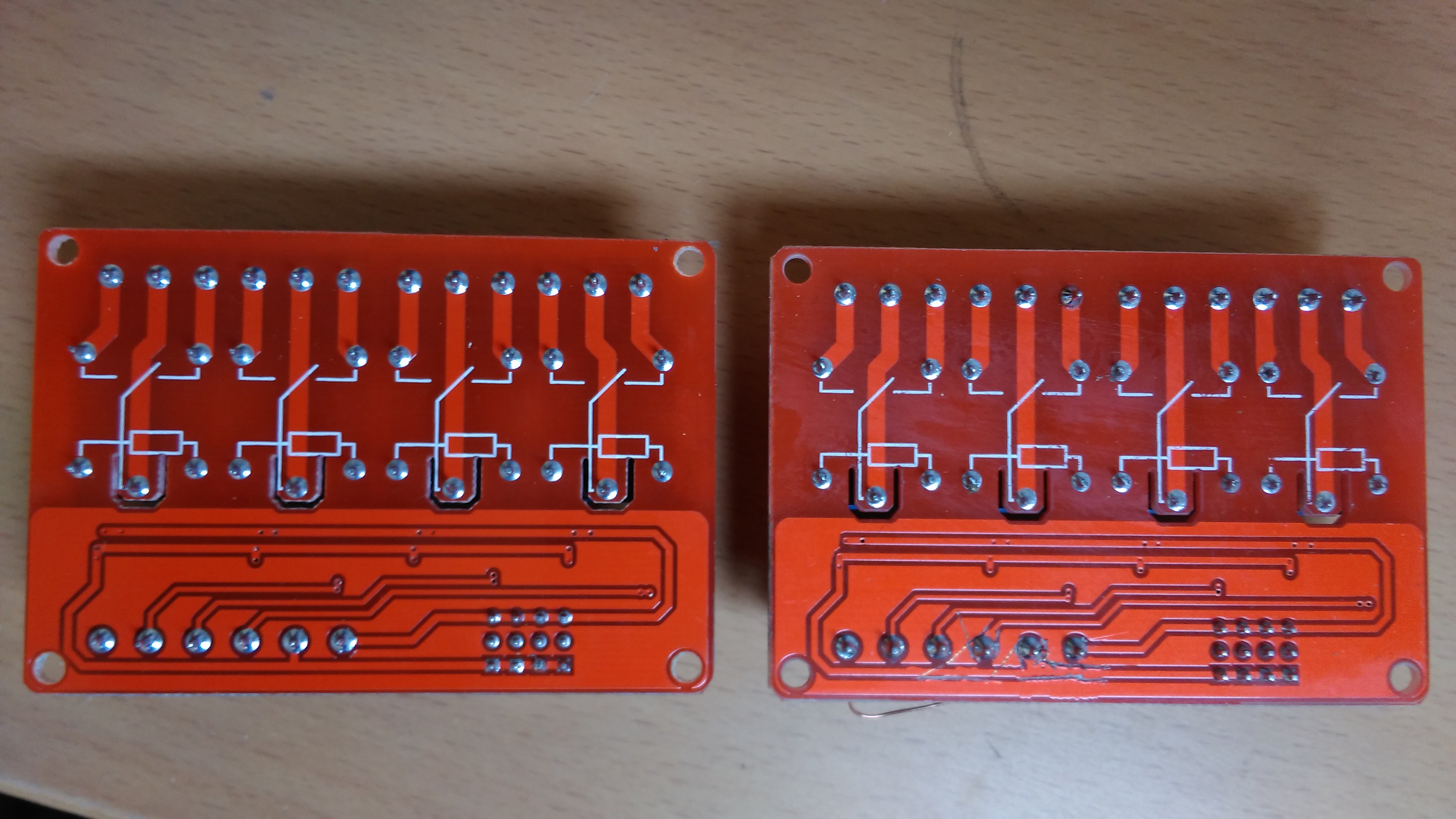
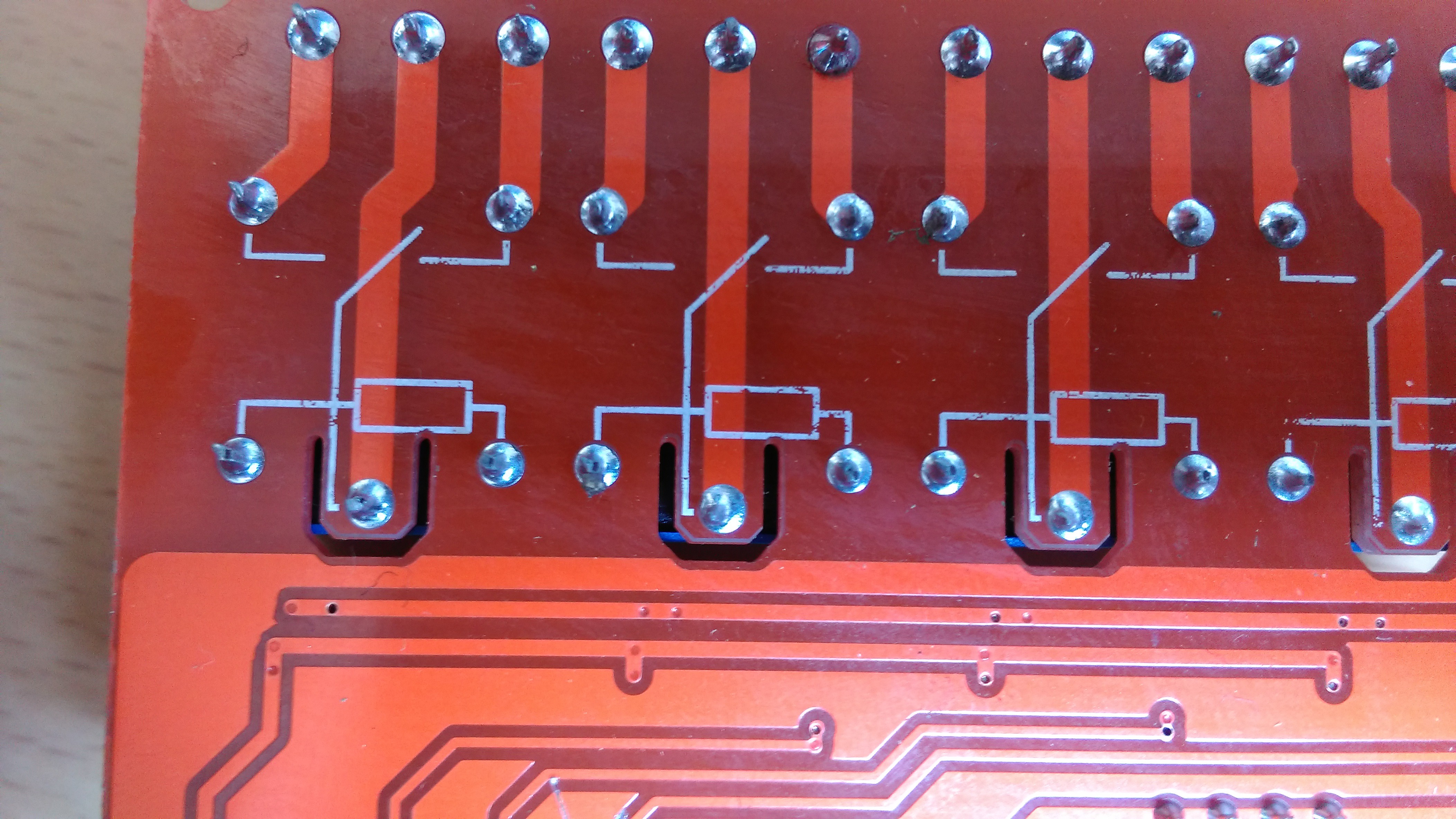
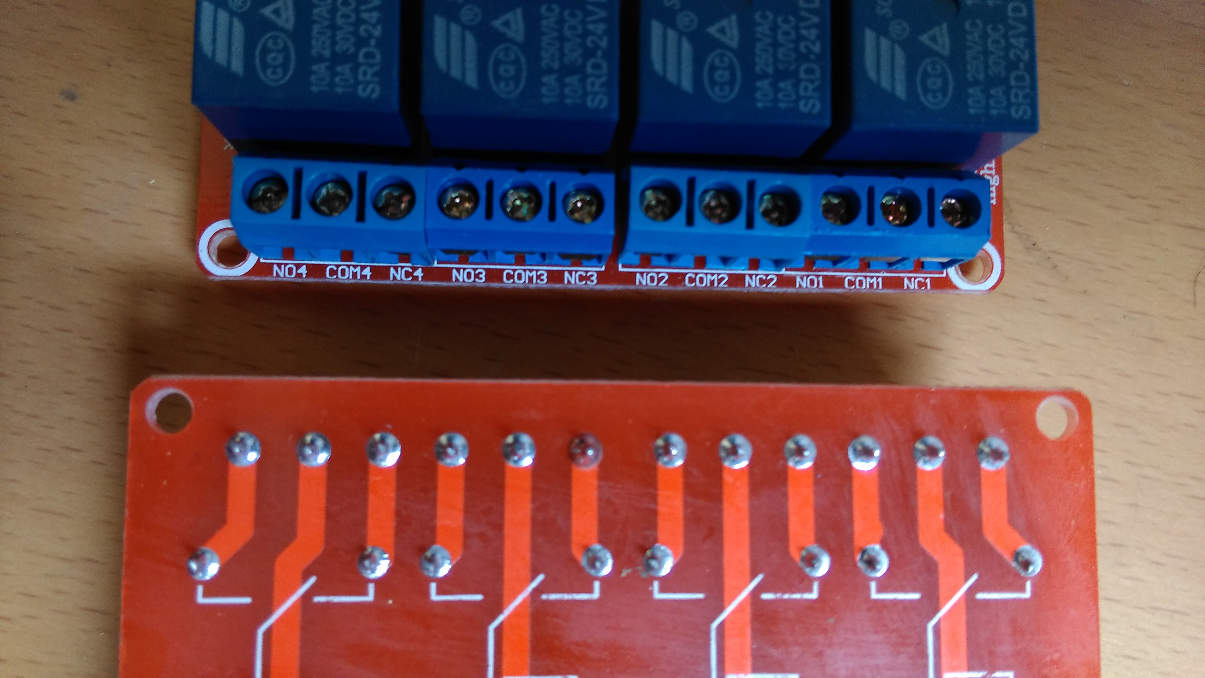
In an ideal world I'd find a nice 24v four relay board that will do the job without need of additional parts, I found one on ebay that looked about right so I ordered a couple for test. They took a while to arrive from China but I decided it was worth a punt to see if it would work out. The jury is still out on this, the boards themselves look fine in terms of track spacing and isolation:
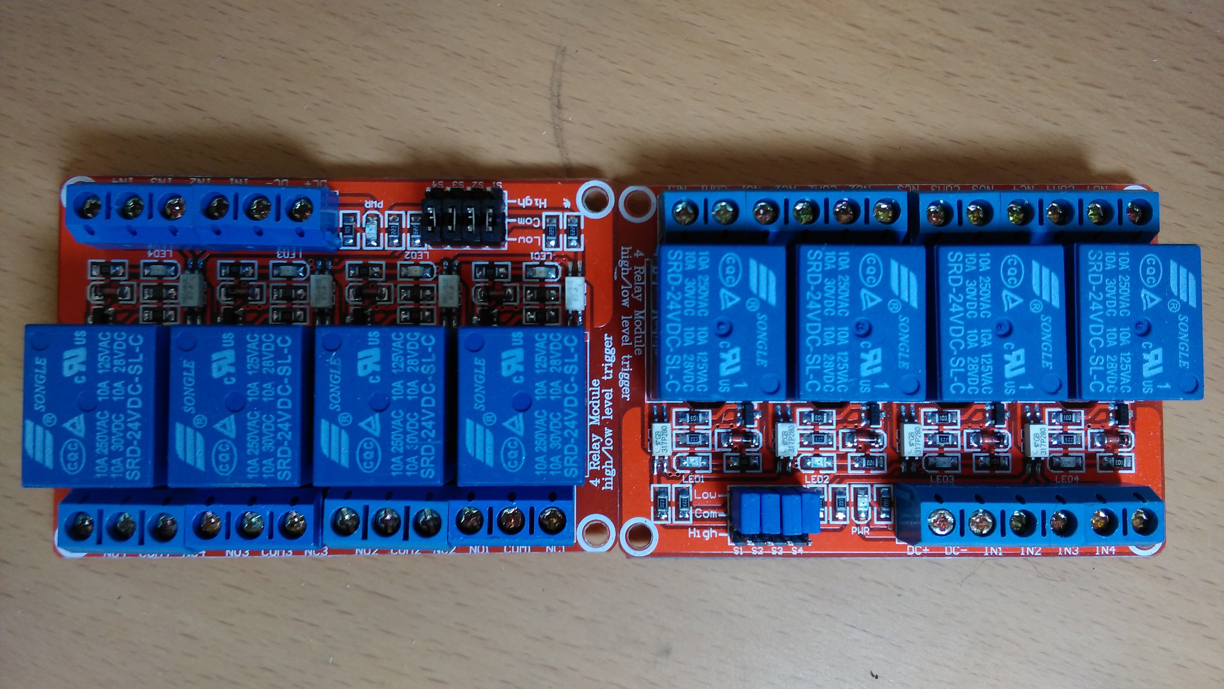
Testing gives me similar data to the Pololu modules.
Here are the figures:
Testing of relay modules
| Module | Trigger voltage | Trigger current |
|---|---|---|
| 5v Pololu rly01a | 5v | 0.05mA |
| 24v ebay module | 10v | 0.4mA |
Mounting the modules
Unless the modules are designed for DIN rail use, your next problem is how to mount them. I'm a member of the Lancaster And Morecambe Makers (http://lamm.hackspace.org.uk/) and we have 3d printers, so I asked Tom to design me a holder for the four Pololu modules to DIN rail mount them. I've been poking him to write a blog post on it for a while but he's not gotten to it yet so I'll have to post for that when he gets his finger out :)
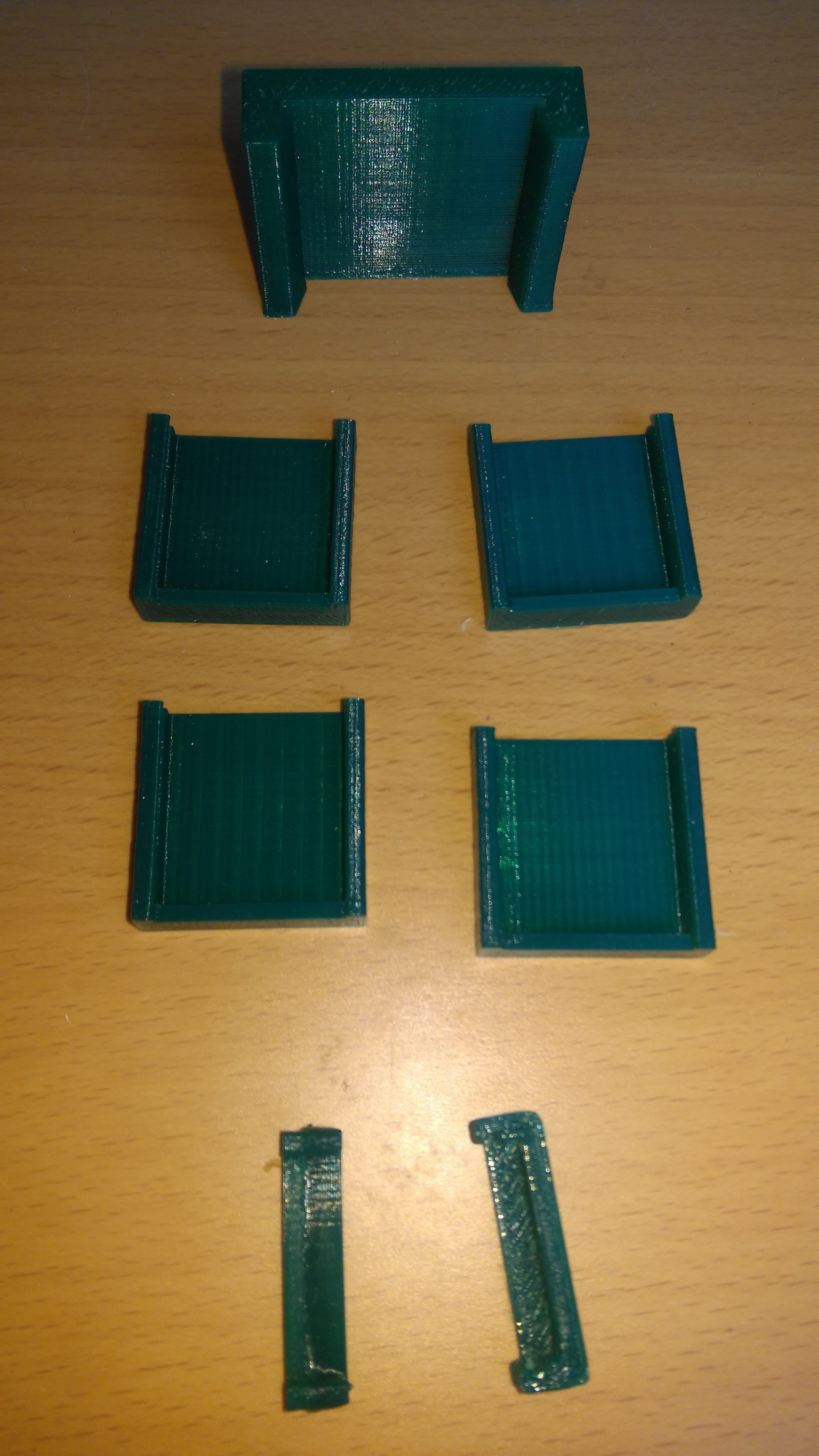
The top centre part is a DIN rail clip, the others are various iterations of single module holders.
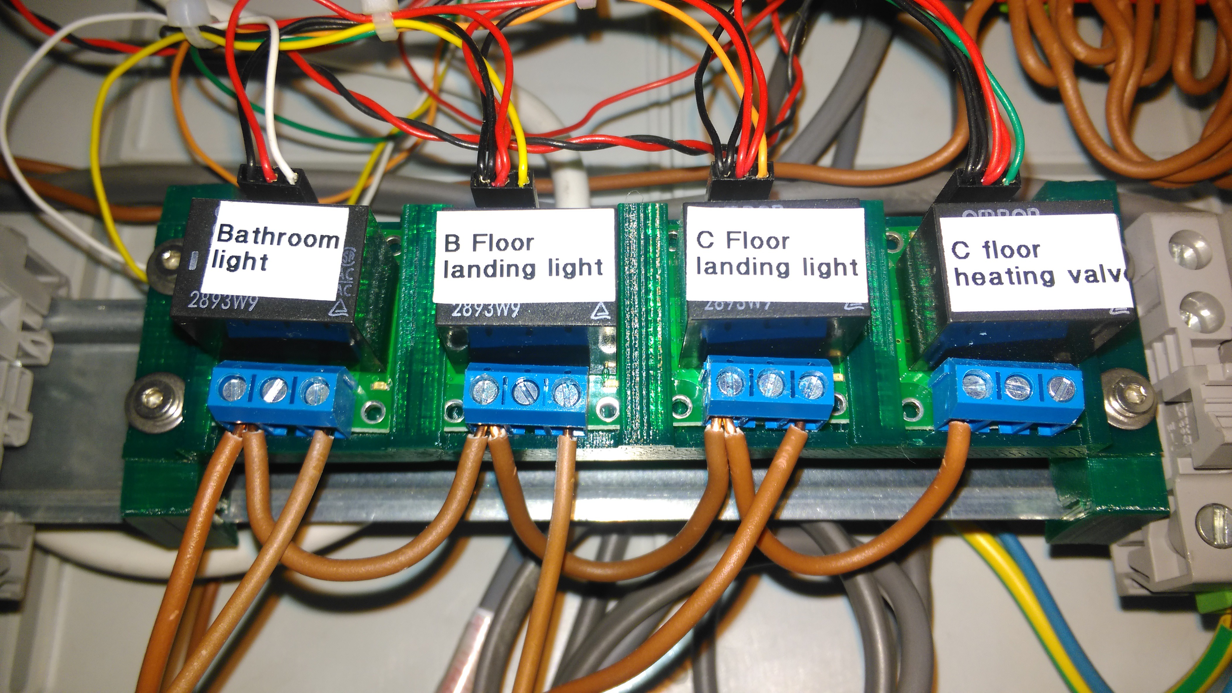
And that's the four module holder with the relays installed and a DIN rail clip mounted at either end.
Software
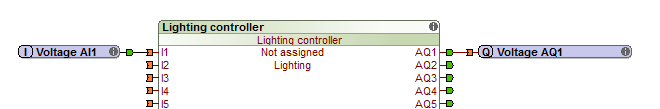
Having checked the relay modules won't blow up your Miniserver or Extension, we've wired it all up and we're ready to program it. Lighting controller, input, output and we're done!
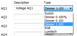
Actually, not so much. I started to get a headache at this point as I just couldn't work out why this didn't work as expected. When I originally mentioned that I was using Linux, I mentioned that there was a gotcha that affects the lighting controller block..... that's what we're seeing here. If I fish out a Windows machine and open the configuration, I can double-click the block and get more information on things like Outputs, Scenes and Favourites. Here's the outputs tab for you to guess at the issue:
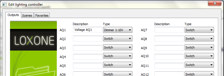
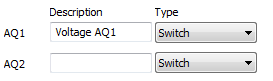
The issue is that if you connect a lighting controller block to a digital output, it knows that the digital output is a 'Switch and can only be in one of two states. If you connect it to an analogue output, then it assumes that the thing you're connecting it to is a 'Dimmer 1-10V'. For this to work we need to change that to be 'Switch' or the thing will behave really oddly and you'll spend a couple of hours trying to work out what the hell is wrong. I encourage you to take a look at the Testing area of Loxone Config and specifically the 'Start Liveview using the current file', had I done this sooner I would have seen the voltage on the output gradually rising while I was pressing the button rather than going straight from zero to five volts.
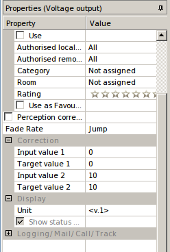
Five volts? But the analogue input goes up to ten! Yes, and if you allow the analogue output voltage to go up to ten, the bloody 5v relay module brns out in our test environment on the bench. Let's not do that, replacing hardware is expensive. To limit that to five volts we need to change configuration on each of the analogue outputs:
Here's the defaults for an output:
And here's our changed one:
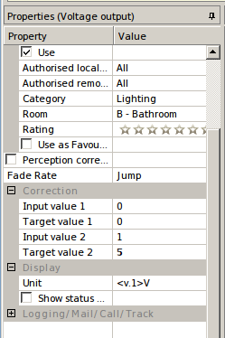
Specifically you're looking to change the following:
- Input value 2 - 1
- Output value 2 - 5
- Unit - <v.1>V
Remember to do this for each of your outputs and hey presto you just won four additional mains capable outputs!
This hack isn't for everyone, unless you understand how the testing was performed in order to check on current limits, you could seriously damage your Loxone equipment. Don't attempt this without checking the kit you buy thoroughly for this and for safety. I've chosen to use the Pololu modules from UK supplier Cool Components for my first attempt at this, but I will be trying the 24v modules from China with my next expansion module installation. When I do that the 5v configuration on the output won't be needed and neither will the switched mode PSU module which looks unsightly.
My reasons may not be your reasons.
Thanks to people who've commented and poked me to remind me I should be posting more, it's good to know that people are reading and enjoying my notes :)
Next time we'll talk about cabling and how to make it look fabulous!
Discussions
Become a Hackaday.io Member
Create an account to leave a comment. Already have an account? Log In.