Okay, I know I said "Next up, doing something other than trying to display '65'." That wasn't what was next.
First up, I worked with using the CH340 serial to USB chip that is on my VISduino to talk to RealTerm on my PC. I was succesffully able to transmit "Hello World", so now I'm ready to send an diagnostic information over it.
Then, after watching this video, I got to wondering how long my display loop was actually taking. So I started off on a journey to figure that out. I also did manage to read through the u8glib documentation, which explained why the RAM usage for u8glib was smaller than the adafruit library. The u8glib can be configured for different page sizes. This is what the whole 'picture loop' is about. If your page size is less than the size of the display, then the loop makes it draw things more than once but sets the display boundaries to cover a new part of the display. This increases the time to draw the display ( since you've got to draw everything more than once ), but divides the memory requirements by the number of pages you're drawing. A 128x64 monochrome display takes (128x64/8) = 1024 bytes in RAM. My code is using the 128 byte page size, so it runs through the loop 8 times.
I suspect that the time that the actual drawing takes is pretty small. The most time is likely spent transferring things over IIC. With the bus running at 400 kHz, it takes at least (1024*8/400000) = 0.02048 ms to transfer one 'display'. Since there's no DMA on the AVR, the processor sits there waiting to place each byte into the transmit register.
So, how long does it take my code to run? I don't know yet. I got sidetracked into the timers, then my wife had our 5th child, so I'm just now getting back to it. I did, however, manage to get Timer0 to toggle an output pin. This also gave me a chance to use the nifty Mobile Studio IOBoard to view the waveform. This is the first time I've had a chance to use the board for something real, and it was nice to see that it worked. Although viewing an 8 Hz waveform isn't taxing it. :)
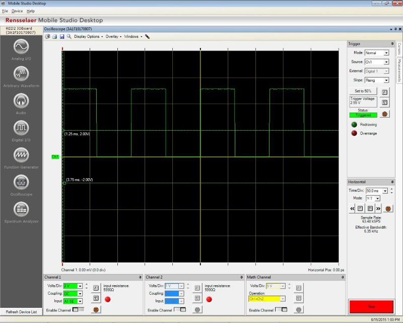
Next up, I want to play with the timer registers and prescalers to get the timer frequency to be in a useful range for measuring the time it takes to display a page. Toggling the pin isn't needed for that timing, but it's a good way to verify that the various prescalers are ending up with a value that I think they should end up with.
Discussions
Become a Hackaday.io Member
Create an account to leave a comment. Already have an account? Log In.