Last time I found that it took about 159 ms to update the display. I have ordered 2 new displays with an SPI interface, they'll hopefully show up in a few weeks.
I wanted to take a look at the actual signals going to the display to see if there was any unneeded delays or inefficiencies. So I pulled out my trusty fx2lafw logic analyzer (also known as a Saleae Logic clone). Running this with the PulseView Windows program from the sigrok project, I used the I2C protocol decoder to easily see the data that was being sent across the IIC bus.
I looked at the data sheet for the ssd1306 controller that is on this board. I kept getting tripped up by its description of the Co bit of the control byte:
"If the Co bit is set as logic “0”, the transmission of the following information will contain
data bytes only."
This seemed to somewhat duplicate the function of the D/C# bit:
"The D/C# bit determines the next data byte is acted as a command or a data."
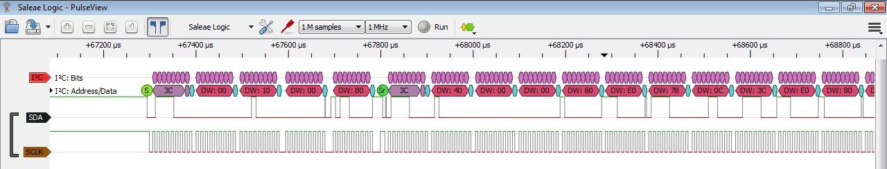
Reading this page, the author clearly talks about the Co bit as being a continuation bit, which is what the bit is described as at the top of Figure 8-7 in the data sheet. That seemed to make more sense. So first the device address is sent (0x3C), and then the control byte indicates that the following bytes will be a stream of commands. Those commands basically set the writing to begin at the start of the display memory. In the next transfer, the device address is again sent, but then the control byte indicates that it will be data that is following. Then there's a long stream of data bytes.
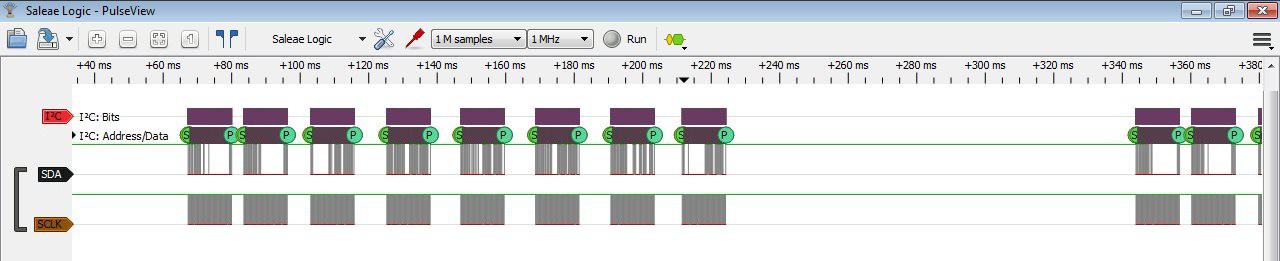
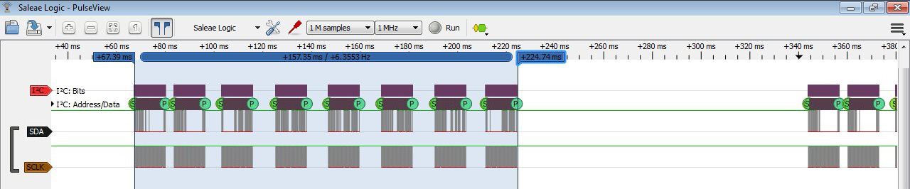
of these transfers. Since we have a page size of 1/8 the display size,
there are 8 transfers.
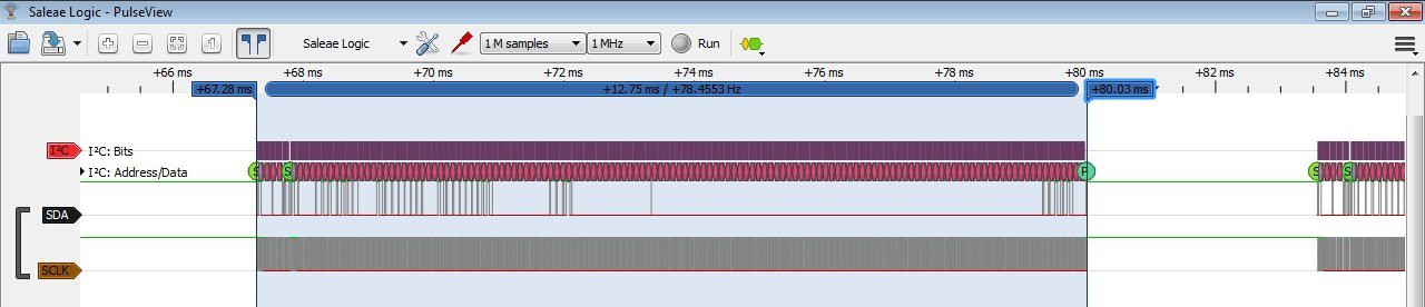

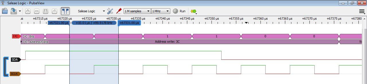 This final image holds the key to the slow performance, though. The time/frequency shown is that of the data clock, which is only 100 kHz. I don't know why I initially thought the transfers were at 400 kHz. That clearly is not the case. And looking at the u8glib code, it clearly chooses a clock frequency of 100 kHz if the U8G_I2C_OPT_FAST option is not passed. So, the next step is to rebuild the code using the U8G_I2C_OPT_FAST option and see how it does. That will have to wait until next time.
Currently, the transfer time it 8*12.75 ms = 102 ms. The drawing time shouldn't decrease, but that transfer time should. Moving to the 400 kHz clock should drop it to 102 ms/4 =25.5 ms. Combined with a combined drawing time of 8*3.57 ms = 28.56 ms, that should be a total of 54.06 ms for the update.
Discussions
Become a Hackaday.io Member
Create an account to leave a comment. Already have an account? Log In.