 alpha_ninja
To begin with, I now have a twitter account. I'll be using it mostly for posting minor progress updates, so feel free to check it out : @not_beta_ninja
Now, I'd like to apologize for taking so long to post this (well, nine days. It could be worse :] ). Anyway, here's the board assembled and sanded, fit in a PCIe x1 connector. I decided to put the power pins on the back because they would otherwise be blocking the ICSP pins. Design flaw, maybe, but meh. This is just a prototype ;)
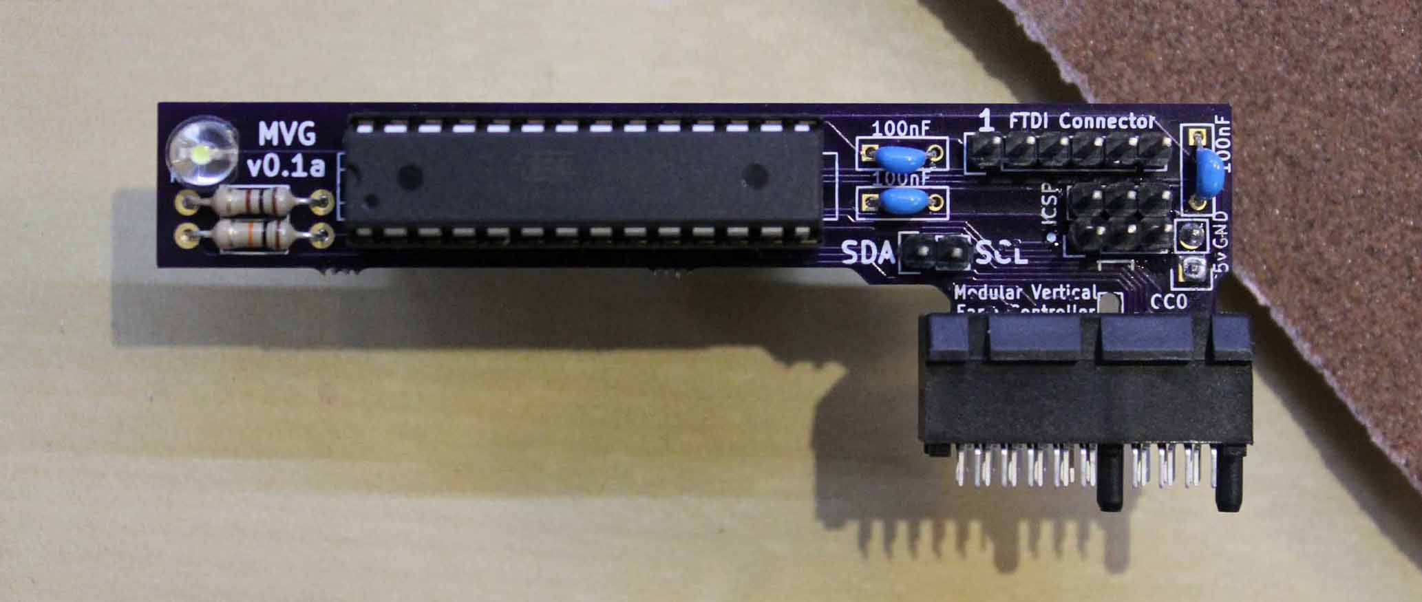
It's a pretty tight fit, and one of the boards required a tiny bit of additional sanding in the cutout just to fit, so I'm going to make the connector a bit thinner. No other complaints on the boards though—they came out great!
Now, on to testing.
I began with a simple power-on test. Worked! (I preloaded the chip with a blinking sketch with an Arduino NG, using the excellent barebones ATMega board files for the Arduino IDE)
I continued with testing FTDI—no problems. I'm pretty happy I didn't swap TX and RX :P
Then, I tested the ICSP. That worked great too. I think I'm going to leave out the FTDI connector on future boards, simply because it's not really necessary. TX and RX are still in the connector design, and since I want to keep the UART broken out, I'll just leave that as it is.
Finally, I loaded up my I²C sketch. It worked communicating with an Arduino UNO, except for a small bug that was quickly squashed ;)
Also, I just checked the resistance through the connector. I'm getting about 0.3 Ohms, which is great.
What I'll be working on next is:
- LED control—I'll probably use some white LED strips I have laying around
- Solenoid control—I have no clue what to test this with, so ordering one or two of those valves from ebay is probably the easiest solution.
- Connector board—I've already designed the connector footprint in KiCad (as always, ask if you want any files!) but I want to get those other things done first.
Thanks for reading, have a nice day (or night!)
Edit 2015-05-26: 0.3 ohms, not 3 ;)
Discussions
Become a Hackaday.io Member
Create an account to leave a comment. Already have an account? Log In.