 Dominic
Arduino sketch can be found here: https://github.com/dpeters1/NeoPixel_SmartWatch
0%
0%
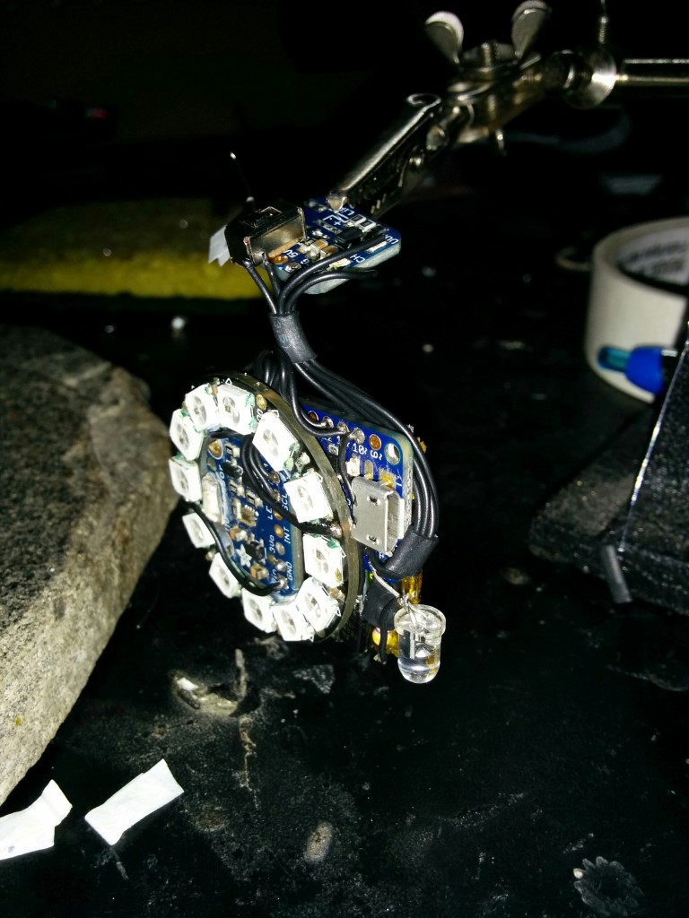
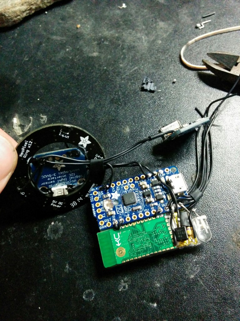
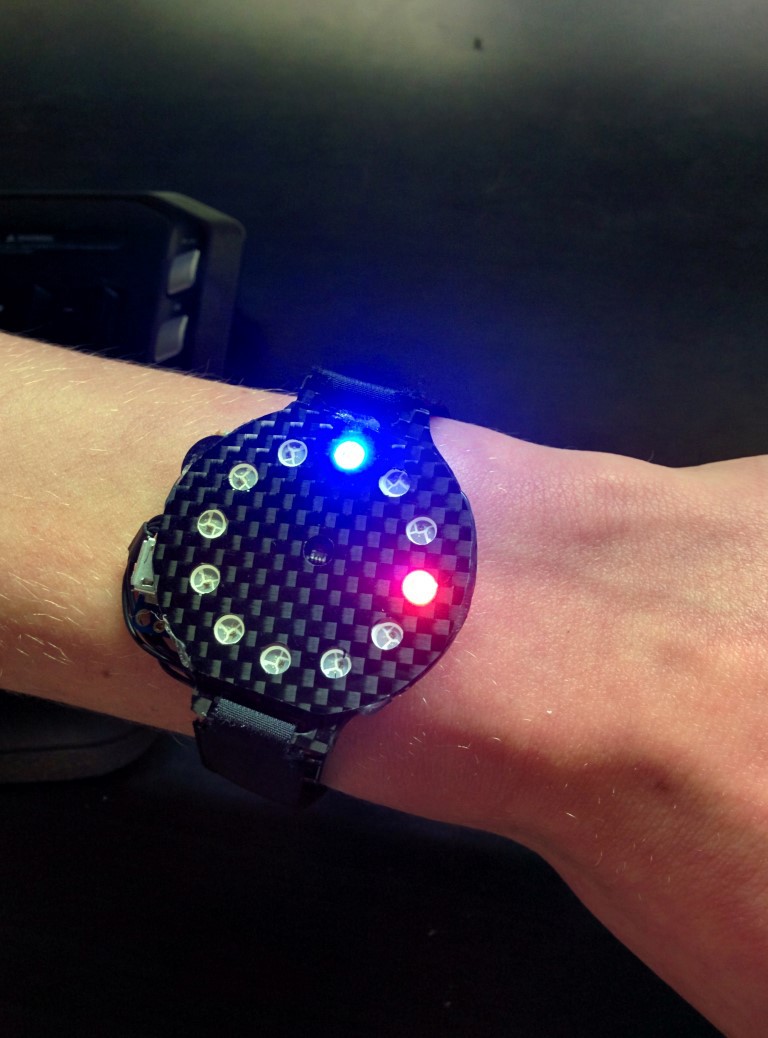
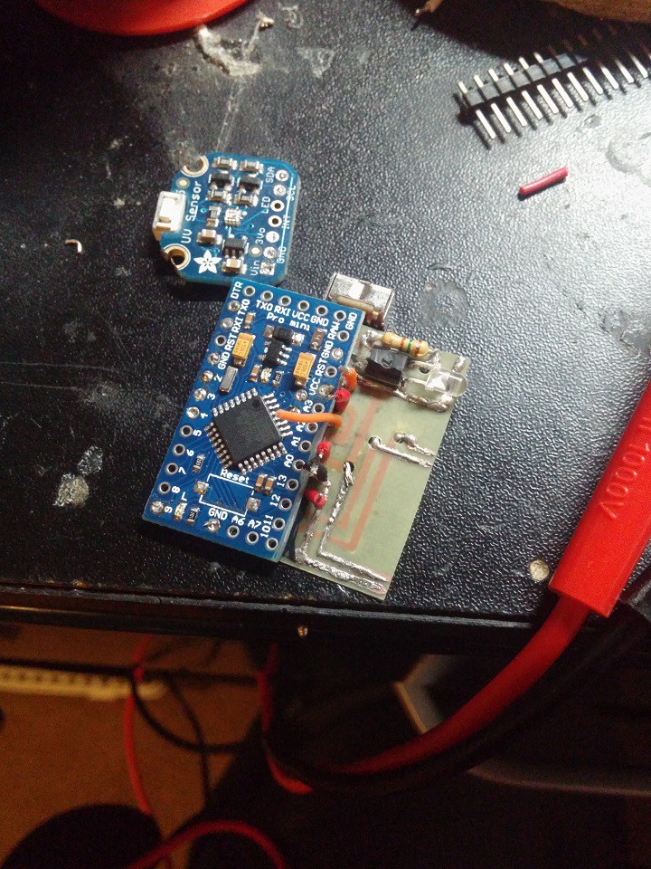
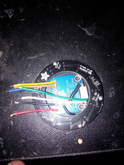
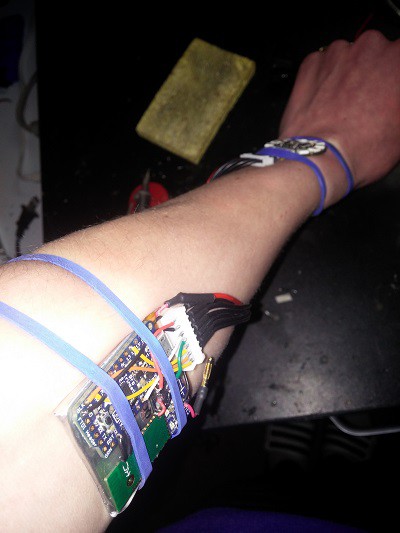
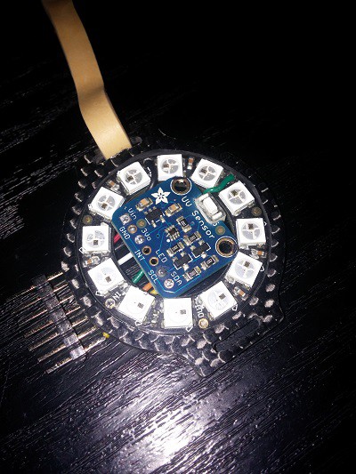
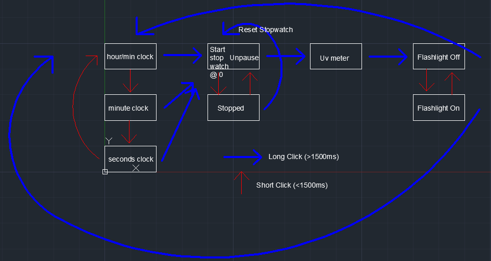
NeoPixel SmartWatch
A first attempt at a wearable that interacts with Android notifications and has a few other neat features.
Become a Hackaday.io member
Already have an account? Log in.
Just one more thing
To make the experience fit your profile, pick a username and tell us what interests you.
Pick an awesome username
hackaday.io/
Your profile's URL: hackaday.io/username. Max 25 alphanumeric characters.
Pick a few interests
Projects that share your interests
People that share your interests
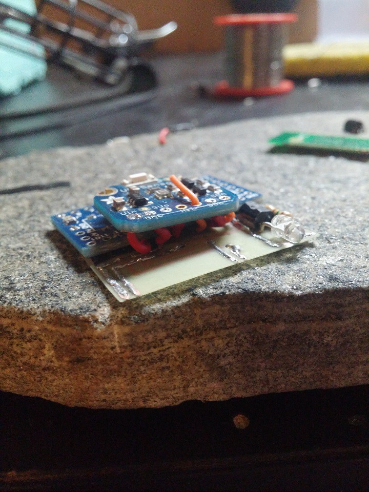
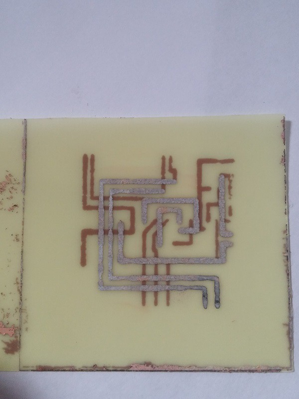
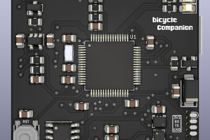
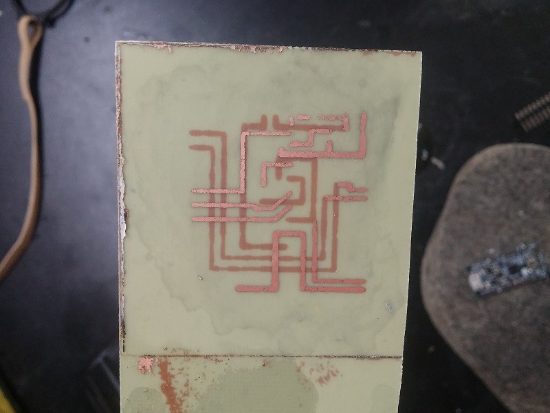 (Pic is before tinning traces)

 Matias N.
 JF
JF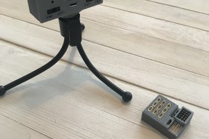
 Grayson Schlichting
can i send step by step navigation directions from the smartphone to Arduino?