 Justin R.
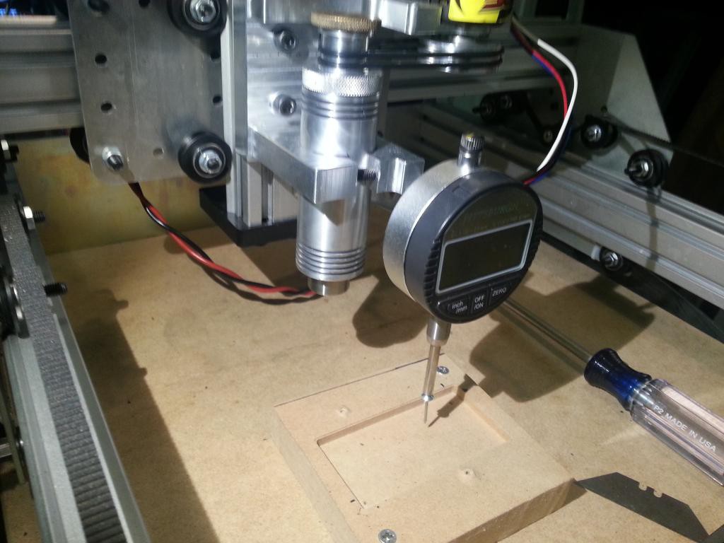
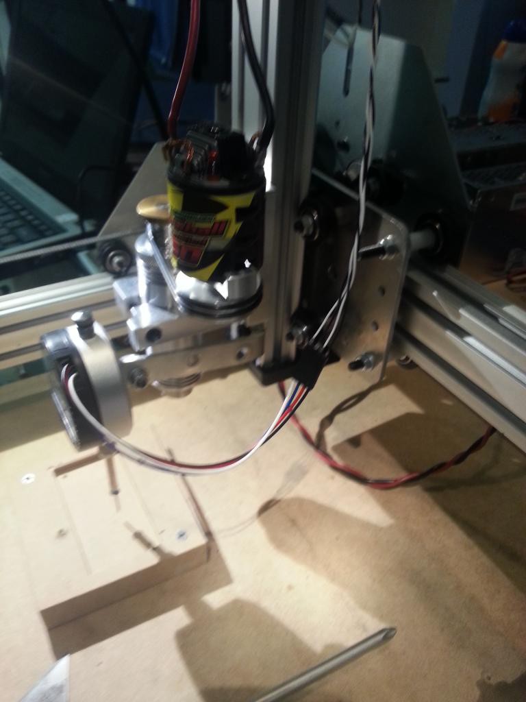
Problem: When using my CNC router to engrave or route circuit boards, I always tend to run in to problems with the work piece not being completely flat or parallel with machine axes. This leads to changes in the depth of cut which are typically quite shallow for these operations. This causes the copper layer to not be cut all the way through for circuit boards, or if engraving plastic, will cause the plastic to melt if the depth of cut increases too much. Solution:
0%
0%
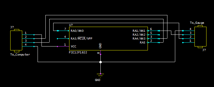
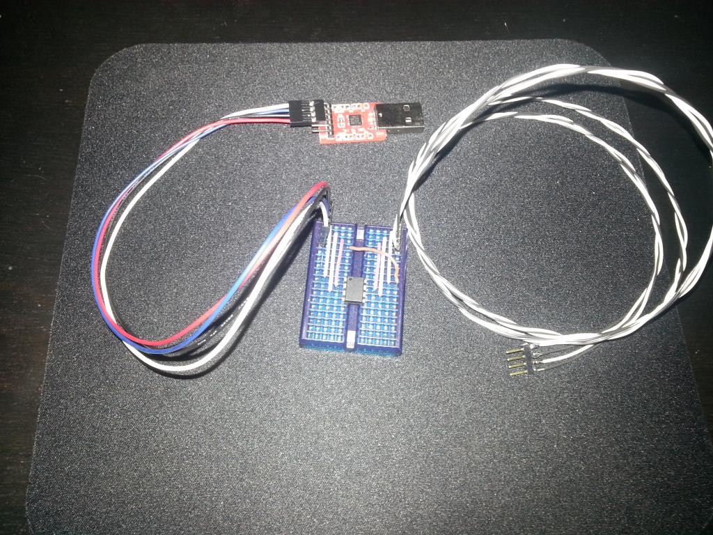
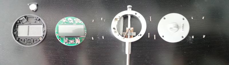
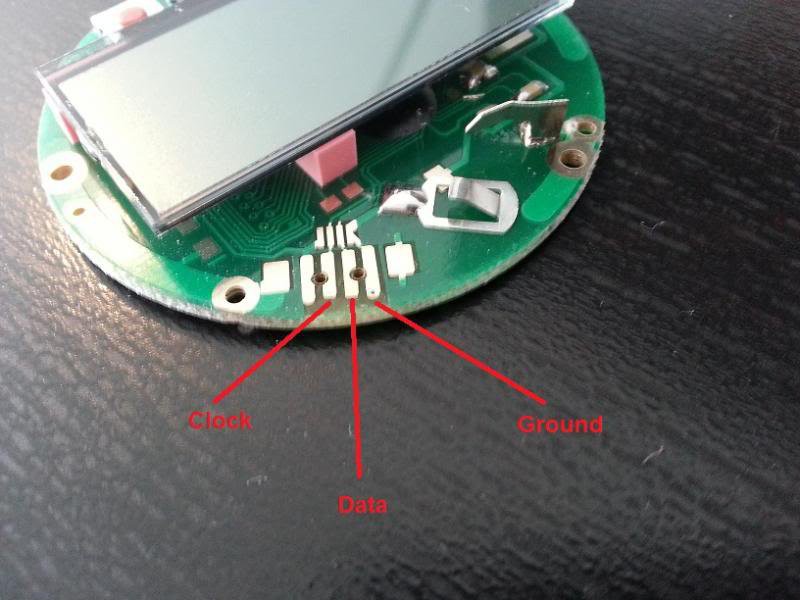
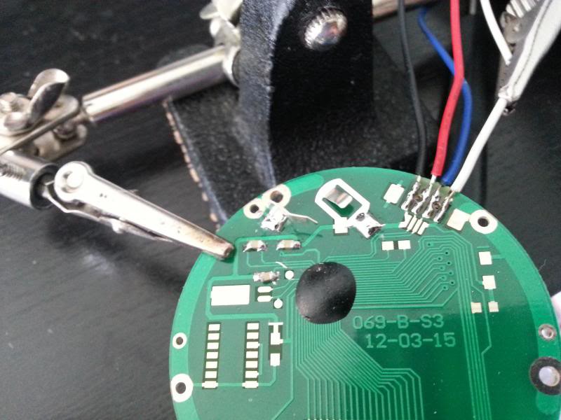
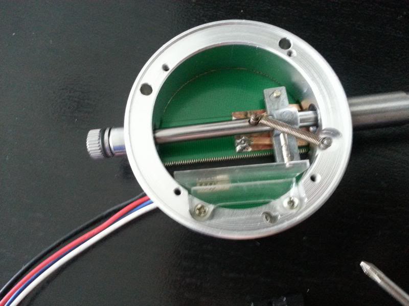
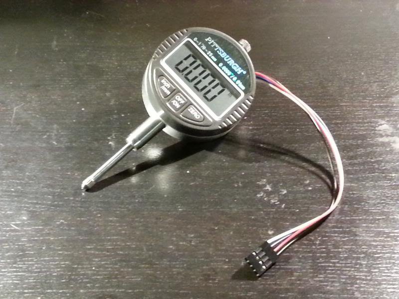
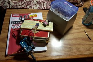
Digital Dial Indicator CNC Surface Probe
Using a cheap digital dial indicator interfaced with CNC machine to map 2D surface. Progress: Almost Done
Become a Hackaday.io member
Already have an account? Log in.
Just one more thing
To make the experience fit your profile, pick a username and tell us what interests you.
Pick an awesome username
hackaday.io/
Your profile's URL: hackaday.io/username. Max 25 alphanumeric characters.
Pick a few interests
Projects that share your interests
People that share your interests


 BDM
BDM
 George Gardner
 Rowanon
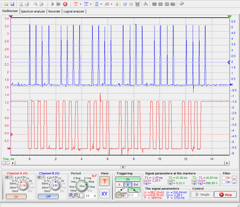
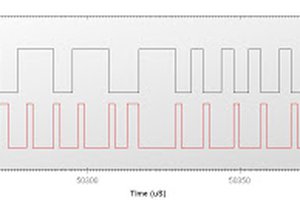
I have got this working up, but i am getting non linear data due to inductive noise in the system.
Dial didn't get reset though values received are started from zero in the middle of process. Any solution?