 Justin R.
To convert the low voltage (~1.3V) custom protocol output by the dial indicator to something that will be readable by the computer I have chosen to use a PIC microcontroller. Specifically, I will be using a PIC12F1822 because it's cheap, small, well featured, and most importantly what I have on hand currently. I will be writing the code for the PIC chip in C using mikroC as a compiler.
Goals for this interface:
- Read in data from dial indicator
- Process data
- Send data to computer (via UART)
Chip pinout and the functions I've chosen to use for each pin:

Reading Data from the Dial Indicator
Since the data coming out of the dial indicator only has a voltage of about 1.3V, and I will powering the PIC chip with 5V, I can not simply read the data and clock lines using standard digital I/O reads (FALSE will always be returned since the voltage never gets high enough to trip the TRUE threshold).
Originally I thought I was going to have to use a hardware level converter using a transistor and pull-up resistor, but I have since realized that I can read the data as analog and make my own threshold HIGH and LOW in the software. I was originally concerned that the analog read would be too slow depending on how fast the data coming from the dial indicator is clocked. But it has turned out that it is plenty fast to reliably read the data and clock signals from the dial indicator.
Here is the process for reading the data:
1. Wait for the Clock line to go LOW (it's natural state is to stay HIGH)
2. Repeat 24 times (to read in all the bits of the message):
a. Wait for a rising edge on the Clock line (LOW to HIGH transition)
b. Read the Data line to get the next bit
c. Add bit to cumulative data for this message and shift
3. Process Data (to be covered further down)
4. Send Data (to be covered further down)
5. Return to step 1 to wait for next message
Note: In case we start or become un-synchronized from the data and end up waiting for the next bit of the message which will never come, we will want to have a timeout on step 2a, such that if the rising edge does not come with in a certain amount of time, we abort the current read and jump back to step 1 to wait for the next message to re-synchronize.
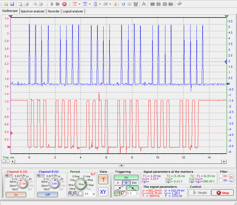
Here is a quick screen shot showing that the PIC chip is able to successfully read the clock and reading the data signals at the correct time. The red line is the Data line from the dial indicator (keep in mind its natural state is HIGH, so this is showing all zeros except the last bit). The blue line is a temporary debug output from PIC chip showing when it detects a rising edge on the clock, and this will be where the Data line is sampled. It looks like they line up quite well.
Processing the Data
Once each individual bit is read in, it will need to be combined with the rest of the bits to build the final data word. This is done in a bit shifting process shown below, which is run for every bit. Keep in mind that the least significant bit is sent first so that determines the direction we need to shift.
Process for building data word:
1. Take the current data bit (which will be 1 or 0) and shift it to the left 24 bits
2. Then add it to the data word
3. Shift the data word to the right 1 bit.
4. Repeat for next data bit
Now that we have the data word, we can extract the measurement portion of it by taking bits 0-19. Taking the modulus of this number and 2 will give the last digit (which can only be 0 or 5, 0="0" and 1="5". Then divide by 2 and this will leave the rest of the digits in decimal form. They can be converted to ASCII characters by breaking them up in to their individual digits then adding 0x30.
Sending the data
The data will be sent to the computer using the built-in hardware UART in the PIC chip. So all that is required is setting up the UART and loading the send register with each character to be sent one at a time.
The PIC chip UART was configured to use a baud rate of 19200, no parity, 8 data bits, and 1 stop bit.
The UART Tx pin on the PIC was connected to the computer using a USB TTL UART.
Here are the results using a terminal program on the computer:
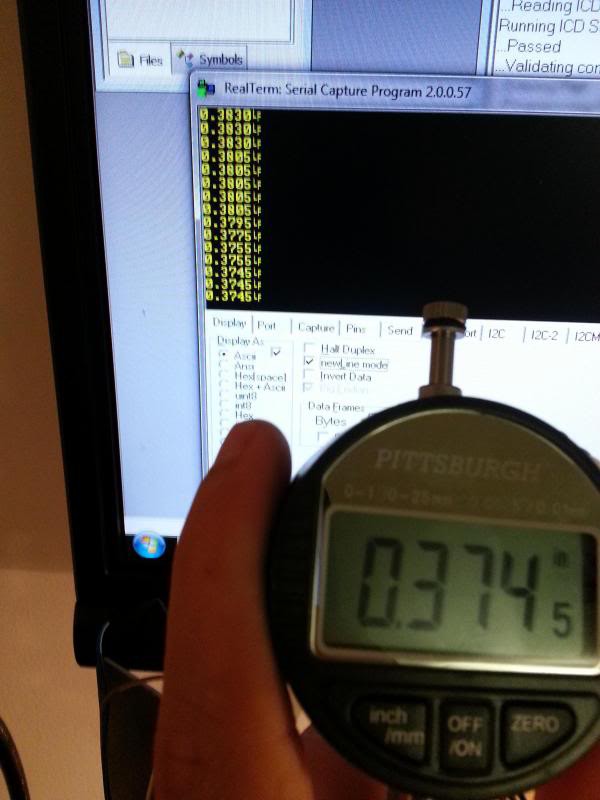
It works!!!
Discussions
Become a Hackaday.io Member
Create an account to leave a comment. Already have an account? Log In.
I have used your method but due to ac noise dial get reset.
when i removed data and clock pins and powering the dial.. dial doesn't reset. please help.
Are you sure? yes | no
Maybe this would help: http://robotroom.com/CaliperCapacitor.html
Are you sure? yes | no
(MSP430 has onboard points 0.25VCC which I would use for this voltage level).
Are you sure? yes | no
Are you sure? yes | no
Are you sure? yes | no
Are you sure? yes | no