In my previous project log I described why I chose stepper motors. You can get them small, and couple them to a screw axis, but you can also be lazy (ahum, practical), and get stepper motors with long screw threads. You often see these types in 3D printers such as those from Prusa.

If you fix the brass (?) nut on the acme thread to something, it will move up and down depending on which way the stepper motor turns. You can see this in the example video below.
These actuators are becoming more and more affordable, and available second hand as well.
How to use them for the mirror
As you can see from the image and video above, the acme screw comes out of the motor and is not hermetically sealed. The plan is to use the solar mirror outside, in whatever weather. So we don't really want rain to come inside. To give the motor some protection, it should be mounted upside down. Any water which miraculously splatters inside can then drip out with gravity.
And if we mount the motors underneath the mirror, then the motor is more protected from rain; the mirror will be a little roof.
But, this does mean that the brass nut has to be mounted quite a distance from the ground, otherwise the end of the rod will hit the ground at some angles.
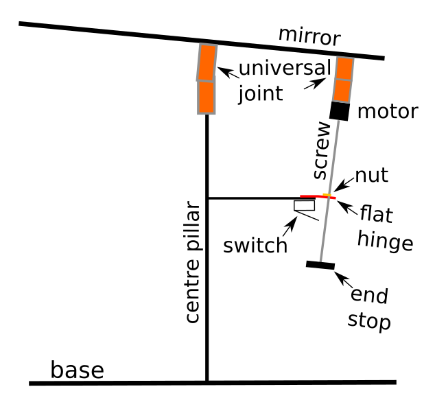
Hopefully the picture above will make this a bit more clear. The centre pillar does not change its length, but has the job of supporting the weight of the mirror. It has a universal joint (called universal hinge , which is a special hinge which can bend in two directions.
Both the motor and the centre pillar have to be mounted with a universal joint. Why? Well for the centre pillar this should be obvious: the mirror has to rotate in all directions. Originally I thought the motor could be mounted with a flat hinge, to constrain the angle only in one plane. But this is the disadvantage of designing in one plane only: I forgot that this joint also has to be able to rotate in all directions, because the mirror tilt! Oops. I found this out when I was constructing the actual prototype.
The task of the flat hinge at the bottom is then to hinge only in one plane, AND to constrain the lead screw of the actuator so that it cannot hinge in the other planes. I haven't quite figured out yet how I would do this easily.
The image above is only shown from one side, with one actuator. But in reality, there will be another actuator, perpendicular (90 degrees offset) from this picture (coming towards you from the screen).
So when the stepper motor rotates, the screw turns, and the nut moves up and down the screw. Because the distance between the nut and the mirror becomes longer or shorter, the angle of the mirror then changes.
Also shown is an end stop, which prevents the nut from falling off the screw when the screw is extended too far, and a switch. The switch is pressed in by the end stop, and this switch is present in the system for two reasons:
1) to know when to stop driving the motor, because the end stop has been reached
2) to know what the zero point of the system is. This is required as a place to start counting motor revolutions from.
In order to automatically (re)calibrate the mirror angle, you just keep driving the motor and rotating the screw until the end stop switch is engaged, and then you call that zero. This is a method commonly used in 3D printers.
Plenty of room should be left between the base and the lower platform, so that at all full extension, the end stop does not touch the ground.
Coming up soon: how are we going to drive all of this? It is supposed to be easy?!?
Discussions
Become a Hackaday.io Member
Create an account to leave a comment. Already have an account? Log In.