 Adnane Belarif
The priciple of this circuit is a rotary encoder switch with a special flip flop design using 6 transistors , the first led lit blocks the second one, and transistor T7 have the role of timing the lighting of the LED's and reseting the circuit when the rotary encoder does not pass voltage.
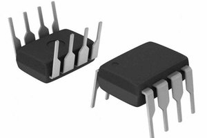
the optocouplers have the role to protect the circuit and it's more stable .
https://www.youtube.com/watch?v=I7yufNY0WOo
NOTE: Exuse my English
Explanations:
- Firstly the Rotary encoder is an electromechanical device that is used to encode a digital signal applied to a microcontroller to define what direction turns and count the number of pulses to manage any system using this principle as the volume control or the frequency control my system uses the analog properties of the rotary encoder to do the same thing, watch this video to understand with this simple installation.
There are 4 steps:
- first step: If you slowly turn from the right direction, the right LED switch on first
- second step: the left LED switch On after.
- third step: the right LED switch off.
- fourth step: the left LED switch off after.
- Then The rotary encoder back to the beginning of its sycle in this position both LEDs are off.
- And if you start from the left, the same steps occur in the opposite direction.
- Then, if you connect the rotary encoder to my flip-flop circuit using six transistors it will block the second LED to turn on, then at each sycle it is always the first LED that will light.
- Now we know which direction turns the rotaty encoder, we have just to put the circuit to its initial state at every sycle, we will do this with the transistor number 7 who have two functions reseting the system and timing the lignting of the LED's every sycle.
- Finaly there are many advantages of this circuit design, its easy to build- cheaper-compact- simple- and does not consume energy in standby state.


 Deion
Deion
 Hulk
Hulk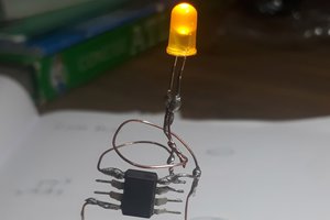
 Amal Mathew
 UTSOURCE
Thank you for the skull , yes you undestoon the circuit very well , this a special design flip-flop circuit associate to Transistor T7 used to generate a pulse every sycle, and by this way reseting the system.
goodluck for you projects , i am following you .