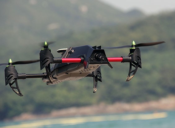
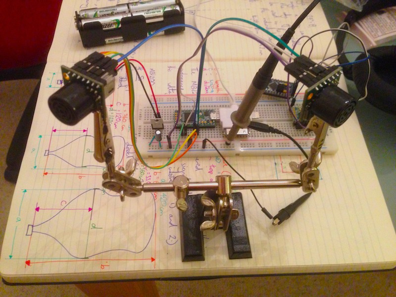
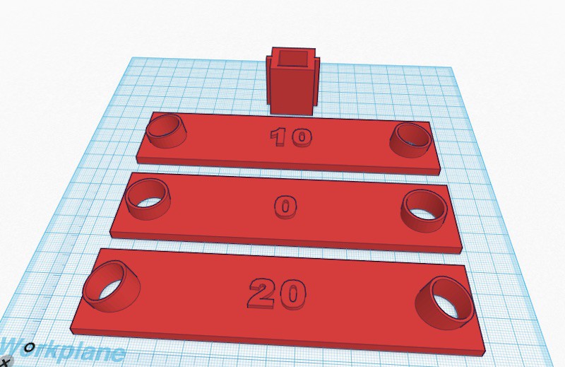
• Interfacing with the Naze32.

    Mr kAr0sh104/20/2015 at 00:39 0 comments

    This might be handy for any RC enthusiasts looking to take over control of the Naze32 flight controller by time cop using a Teensy 3.1. Or any FC that uses PWM signal inputs.

    Firstly, a bit of simple maths, then a code example to get you going.

    The Baseflight firmware, and many others, I'm using with the Naze32 stipulates that it's central 'value' of any signal is '1500', which is the number of microseconds the duty cycle of your PWM signal input has. If you're new to PWM and duty cycles here's a few facts. The maximum is '2000', which would symbolise full throttle, or tilt etc, and the minimum is '1000', these are slightly weird numbers as they're of equal distance from each other, but not from 0 and whatever signal maximum you choose (I went for 3000). Where it gets interesting is how you can simplify the process of connecting to your FC by manipulating the base frequency of your PWM outputs to be a round percentage of the microsecond duty cycles you're aiming for. On a Teensy you use:

    void setup() {
    
    analogWriteFrequency(6, 333); // change PWM frequency to match receiver inputs
    
    }

    There's a very comprehensive reference for all of this on Paul Stoffregen's site here for all the background. Where did 333Hz come from? 3000us in Hertz is 333.3(recurring), just look it up on a converter. This sets us up nicely because when we then want to generate our middle value of 1500us, all we have to do is output half of our maximum PWM signal value, in my case 255. Ie;

    int power = 127; //127 is half the maximum duty value 
    
    analogWrite(throttle, power); // output value for throttle output
    You can modify the resolution of the PWM signal to have a greater integer range, but "if it ain't broke, don't fix it!".

    Next, we need to match the control loop of our FC. This is more just a precaution because I'm fairly certain most FCs 'remember' your last command even if the next one is a little late, but why tempt fate? To make sure the information from your PWM signals gets there on time, no matter what, interrupts need to be implemented to force the microcontroller you're programming to drop everything it's doing and make sure it sends the information necessary to keep your drone in the air. Programmatically, we need four things for that;

    int controlrate = 3500; // control loop time in microseconds (3500us for Naze32)
    
    IntervalTimer updater; // interrupt function label
    
    void setup() {
    
      updater.begin(outputs, controlrate); // begin interrupt timer for FC
      updater.priority(0); // updates to control values take prescedence
    
    }
    So the frequency of the outputs is synced to the FCs control rate, the interrupt is labelled 'updater', it's started like you would a serial connection with 'outputs' as the selected subroutine to jump to - this must not contain any delays - and finally the priority is set. '0' is the maximum priority, so even if another interrupt is running, the updater will override it then return back to it after finishing.

    You can always recognise interrupt-driven code at first glance because it usually has nothing in the main loop :)

    int aileron = 6; // pin to control of the roll of the drone
    int elevation = 9; // pin to control of the pitch of the drone
    int throttle = 21; // pin to control of the upward speed of the drone
    int rudder = 23; // pin to control of the yaw (rotation) of the drone
    
    int power = 127; // power output to the throttle, default: 85 (lower)
    int turn = 127; // rotation value, default: 127 (middle)
    int roll = 127; // roll value, default: 127 (middle)
    int climb = 127; // tilt value, default: 127 (middle)
    
    int controlrate = 3500; // control loop time in microseconds (3500us for Naze32)
    
    //throttle minimum is 1150, middle 1500 and maximum 1850
    //throttle middle is actually 1.5ms or 1500us
    
    // most ESCs have an update rate of 400Hz so the control loop could be reduced to roughly 2500 microseconds
    
    IntervalTimer updater; // interrupt function label
    
    void setup() {
      analogWriteFrequency(6, 333); // change PWM frequency to match receiver...
    Read more »

  • The Collision Detection System.

    Mr kAr0sh104/16/2015 at 21:47 0 comments

    So much to tell, so little time!

    My Final Year Project Open Day is fast approaching so I'm working rather quickly but I'm very confident I can get this done :)

    Firstly, big thank you to the guys at Deviation, they've been a huge help and very supportive with working out the protocol of the previous drones I was using, and even suggesting a new drone to replace the previous - essentially, I did a maximum payload test with the UDI U818A and it tapped out just under 100 grams, far too low to give me any flexibility. So.......enter the Quanum Venture....

    Ain't she a beaut?! I decided early on that this project was not meant to be about building just another drone, anyone with an Arduino and a desk fan can do that, I wanted to give people the option to make their drones so much more. The Quanum Venture I've gone for will have all the ESCs (motor controllers) and the Flight controller (an Afroflight 32, highly recommended and very open) prebuilt and ready to install, I can then send signals to the flight controller to act as the 'brain' of the aircraft and alter it's behaviour. That camera on the front will be switched out for my optical payload.

    My most recent test of acquired hardware was the MB1200 Maxbotix Ultrasound sensors. They will make up the main part of my CAS (Collision Avoidance System) by giving the drone exteroception - allowing it to monitor the environment around it - and prevent it from crashing into anything directly in front or behind it. The MB1200s are absolutely the best choice I've seen so far for this sort of thing; they're industrial-grade, no-nonsense, long-range (about 7.5 metres up to 10) and very easy to interface to. Even if I flew my drone at full speed, roughly 30 mph, it'd still have half a second to react, and with a 72MHz microcontroller like the Teensy that's a really long time.

    Above is my test rig, purely just to get the sensors up and running, however below is the STL of my angular offset rig - to allow me to test which offset will work best. Essentially the biggest problem I can foresee with this system is the dreaded 'blind spot' between the sensors. The human optical system manages this seamlessly but when dealing with an aircraft things need to be a little more definitive, so I'm being very careful with this factor, too closely angled and there will be too much overlap and having two sensors will become pointless, too little overlap and something could slip through the net and the drone could collide with it. This is meant to be a system designed for open air flight, not indoor, so traditional factors of angled surfaces etc don't exactly apply.

    If you fancy picking up a couple of the MB1200 and building something similar, try my test code, just alter the values at the top according to how you wire yours and remember to read the data sheet first!

    int left = 20; // left sensor analogue input
    int right = 19; // right sensor analogue input
    int rightcon = 10; // right sensor control pin
    int leftcon = 7; // left sensor control pin
    int led = 13; // indicator LED on dev board
    
    void setup() {
      Serial.begin(115200); // begin the serial connection
      pinMode(rightcon, OUTPUT); // control pin for right ultrasound sensor
      pinMode(leftcon, OUTPUT); // control pin for left ultrasound sensor  
      pinMode(right, INPUT); // analog input from right sensor
      pinMode(left, INPUT); // analog input from left sensor
      pinMode(led, OUTPUT); // led
    }
    
    void loop() {
      digitalWrite(led, HIGH); // flash the LED
      
      digitalWrite(leftcon, HIGH); // activate the left sensor
      delay(20); // delay necessary to prevent 'cross reading' - see datasheet MB1200
      digitalWrite(leftcon, LOW); // turn off the left sensor
      int leftval = analogRead(left); // read value of left sensor
    
      delay(20); // delay necessary to prevent 'cross reading' - see datasheet MB1200
    
      digitalWrite(rightcon, HIGH); // activate the right sensor
      delay(20); // delay necessary to prevent 'cross reading' - see datasheet MB1200
      digitalWrite(rightcon, LOW); // turn off the right...
    Read more »

  • The RF Protocol.

    Mr kAr0sh104/09/2015 at 20:40 0 comments

    Lots of coffee and staring at a big long list of hexadecimal numbers later, I think I am gradually beginning to recognise a pattern that will lead me to the communication protocol of the drone I'm trying to link to.

    Below is an annotated print-off of the sequence that the TX rattles off when it's paired to a drone. Note the repeating blue boxes? They're the ID packets of the transmitter, presumably to tell the drone that it's still there or to authenticate. Then things get a little odd - the green, yellow and pink headings indicate different starting values for the 'data packets' that are then sent through, packets that contain info like throttle, yaw, pitch etc values. Can you see a pattern in them? I sure as hell can't!

    And then the oddest, the pink box indicates a unique packet sent every fourteenth cycle of data. I have no idea what this is for, but if my comms lecturer taught me anything it's that there's error checking everywhere, so maybe that's it's purpose?

    Time for a quick break, then to press on.

  • Sniffing logic.

    Mr kAr0sh104/09/2015 at 12:32 1 comment

    Crash course in SPI logic sniffing:

    1.) Buy a Bus Pirate.

    2.) Read this page.

    3.) Download this program.

    4.) Open this project in that program.

    5.) Connect your Bus Pirate.

    6.) Hook up the wires to your I/O

    7.) Go to Capture > Begin Capture (re. step 2)

    8.) Pick your device

    9.) Change 'acquisition' settings to match your target

    10.) Press 'capture'

    11.) Say thank you to Greg Whitmore

  • Drone disaster.

    Mr kAr0sh104/09/2015 at 10:28 0 comments

    Hey everyone,

    Quick update - no luck on using the BK2421 so far!

    Moved on to trying a different transceiver, I had an nRF24L01 lying around so thought I'd give it a crack with this code, to no avail - drone still does not pair.

    Took delivery of another two UDI U818As today and will proceed to logic sniff them with the BusPirate and see what I'm doing now. The guys over at Deviation list them as 'unsupported' however, which is slightly terrifying.

    For the moment, however, I'm going to start developing my FPGA+MCU board and leave the transceiver/timevampire as an empty slot to connect the SPI pins to, there's a good chance I might have to change drone or transceiver model suddenly so I think it's best I make that an easy transition.

    Board designs soon.

  • Binding with the drone.

    Mr kAr0sh104/08/2015 at 12:54 0 comments

    MAJOR issues with binding to this little sucker - the UDI 818A. It seems no matter which SPI-based library I use, none of them conform to the correct protocol.

    I've tried the 'HCD' library by GeekPhysical with no luck, double-checked the transceiver was actually working with this code from the guys over at Deviation and the script returns a "NO RX ID - Stopping Bind" serial response, prompting me to think the issue is either the protocol I'm using, which apparently may be different for the UDI 818A from the UDI 818, or I need to alter the code slightly to deal with my drone in regards to timing or addresses etc.

    So why am I going this route rather than just attaching my own board design directly to the motors, and flying the thing myself? Well, the key is who I'm orientating my project towards. The idea is that you can get this payload, attach it to any drone, and wirelessly take charge of it without any invasive alterations to the drone itself, but still giving you higher-level functions similar to if you had actually reprogrammed it completely. There is increasing evidence that this is what industry are doing also, with military aircraft.

    Other aspects of control, like being able to tether several drones to one payload and fly them in a group, could be taken advantage of - one sensor payload to several drones means you could conserve energy and weight, vital if you want to fly long distances or carry one, big, heavy object.

    My weakest subject is radio transmission/ICs so this is going to be a tough start but I'm going to have to do some research into how these guys probe and sniff the protocols the SPI transceivers use. I have a Bus Pirate handy (thank God) and a pretty decent oscilloscope so I'm not showing up empty handed!