0%
0%
JJ Tricoder
Goal of this project is to develop functional Tricoder device, similar to type TR-580.
 jaromir.sukuba
Become a Hackaday.io member
Already have an account? Log in.
Just one more thing
To make the experience fit your profile, pick a username and tell us what interests you.
Pick an awesome username
hackaday.io/
Your profile's URL: hackaday.io/username. Max 25 alphanumeric characters.
Pick a few interests
Projects that share your interests
People that share your interests
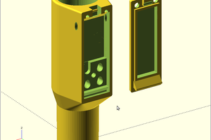
 Julia worked on case design in the meantime.
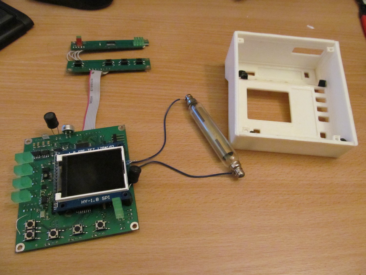
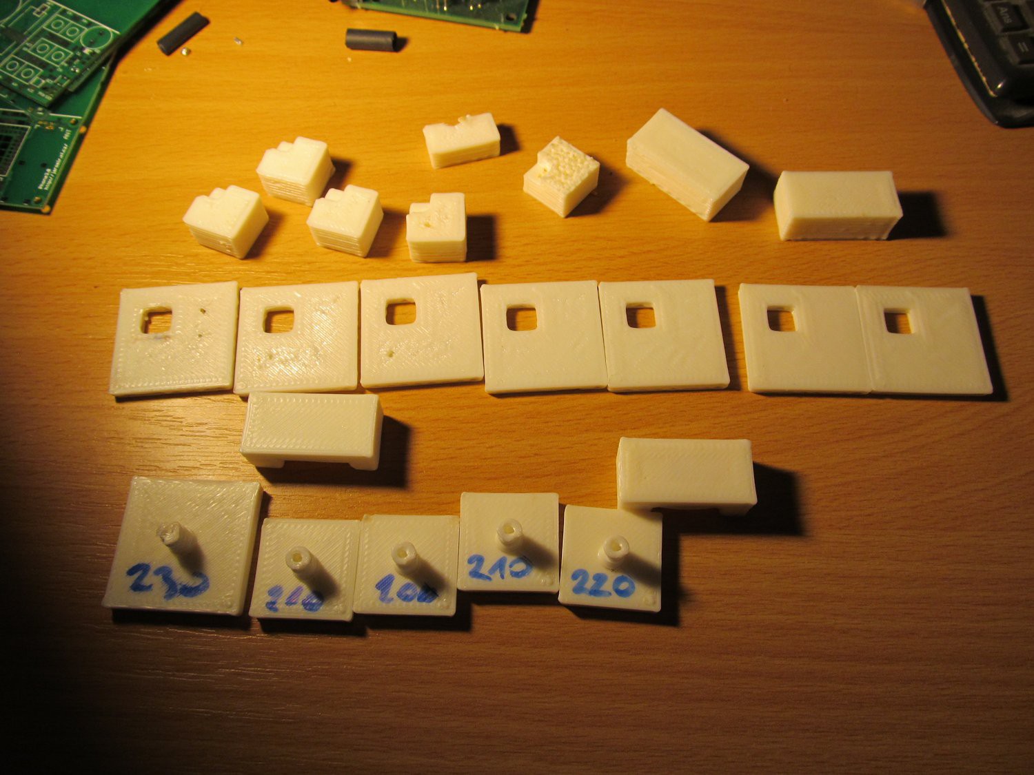
 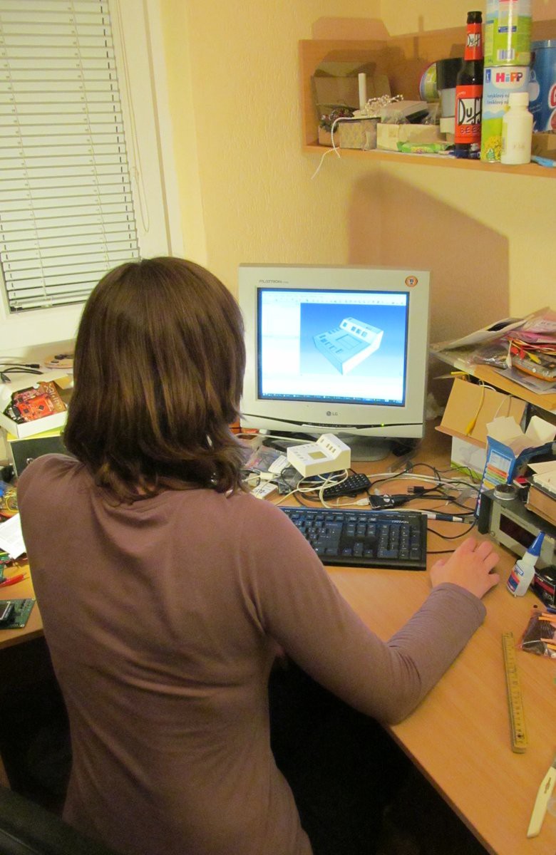 I printed the plastic parts of case
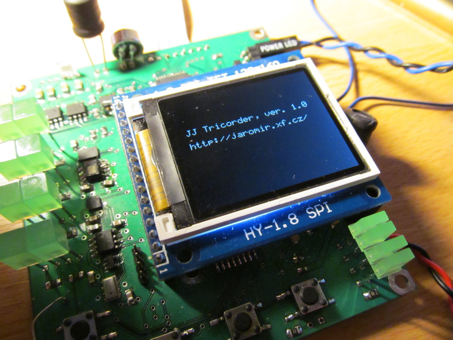
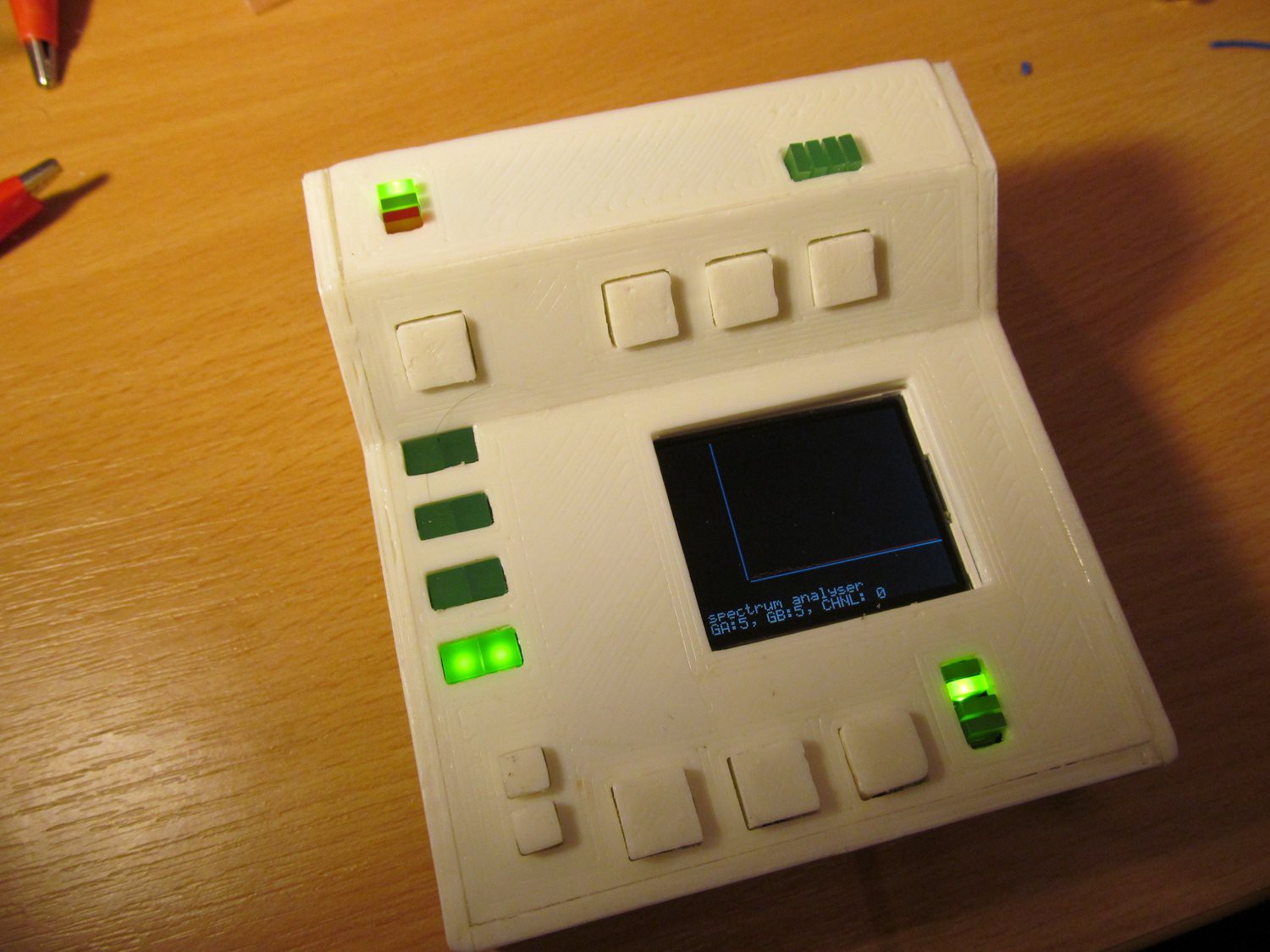
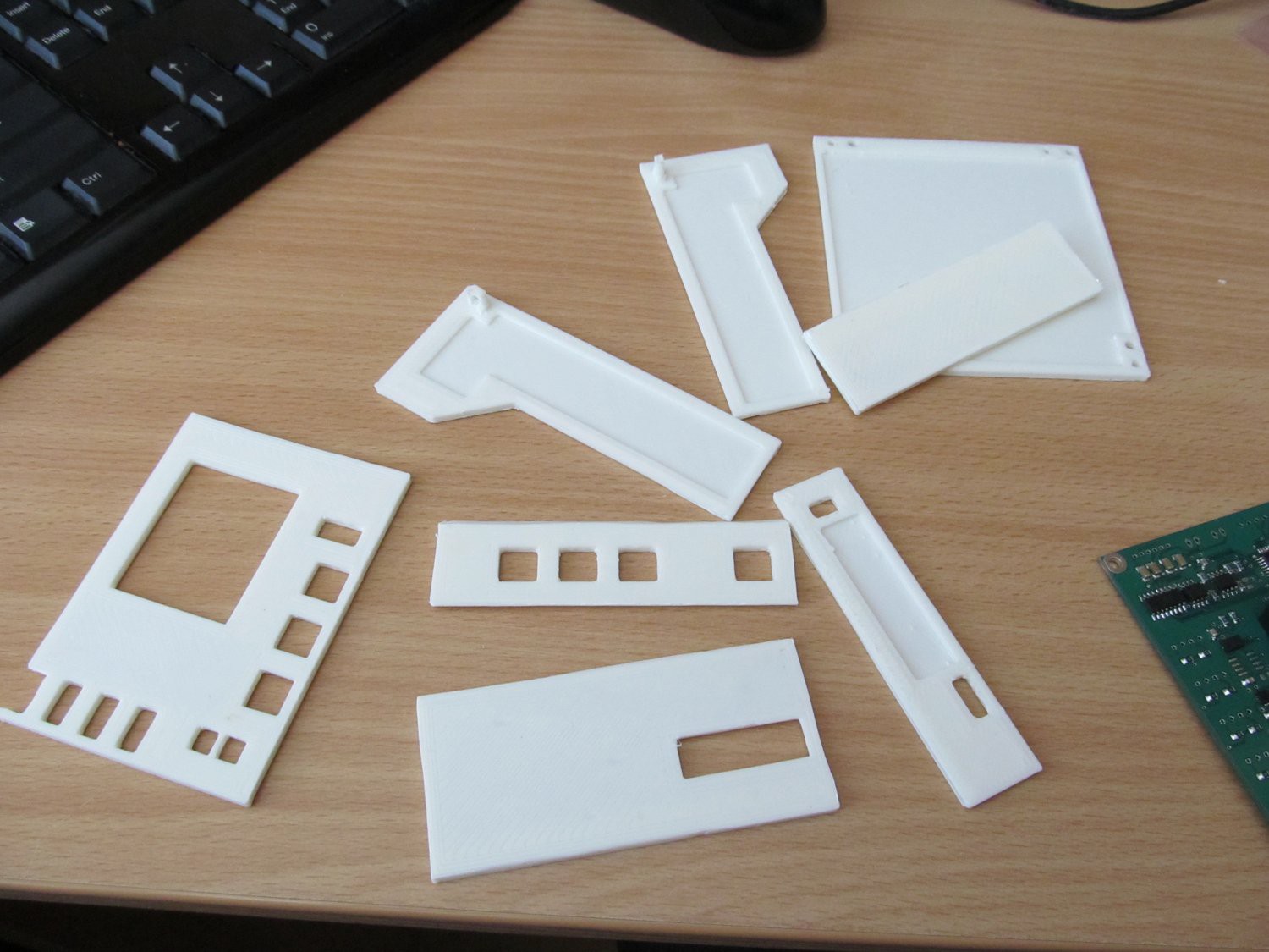 And here it is, when idea comes physical. Yep, that's CRT display.
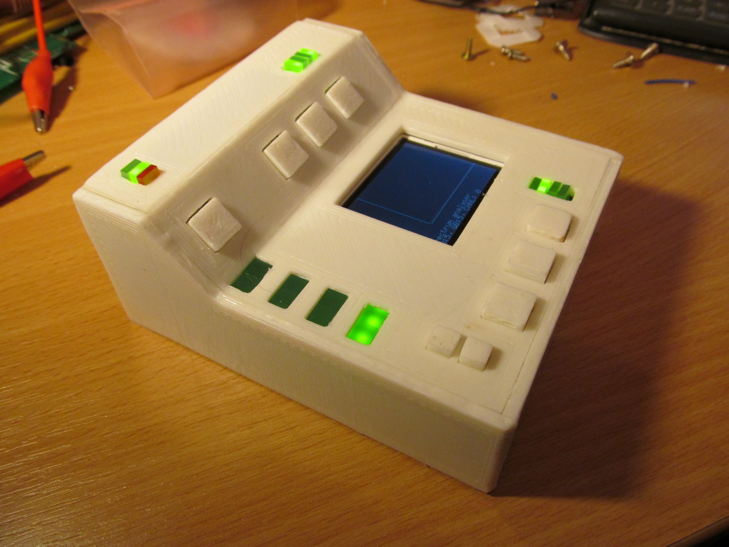
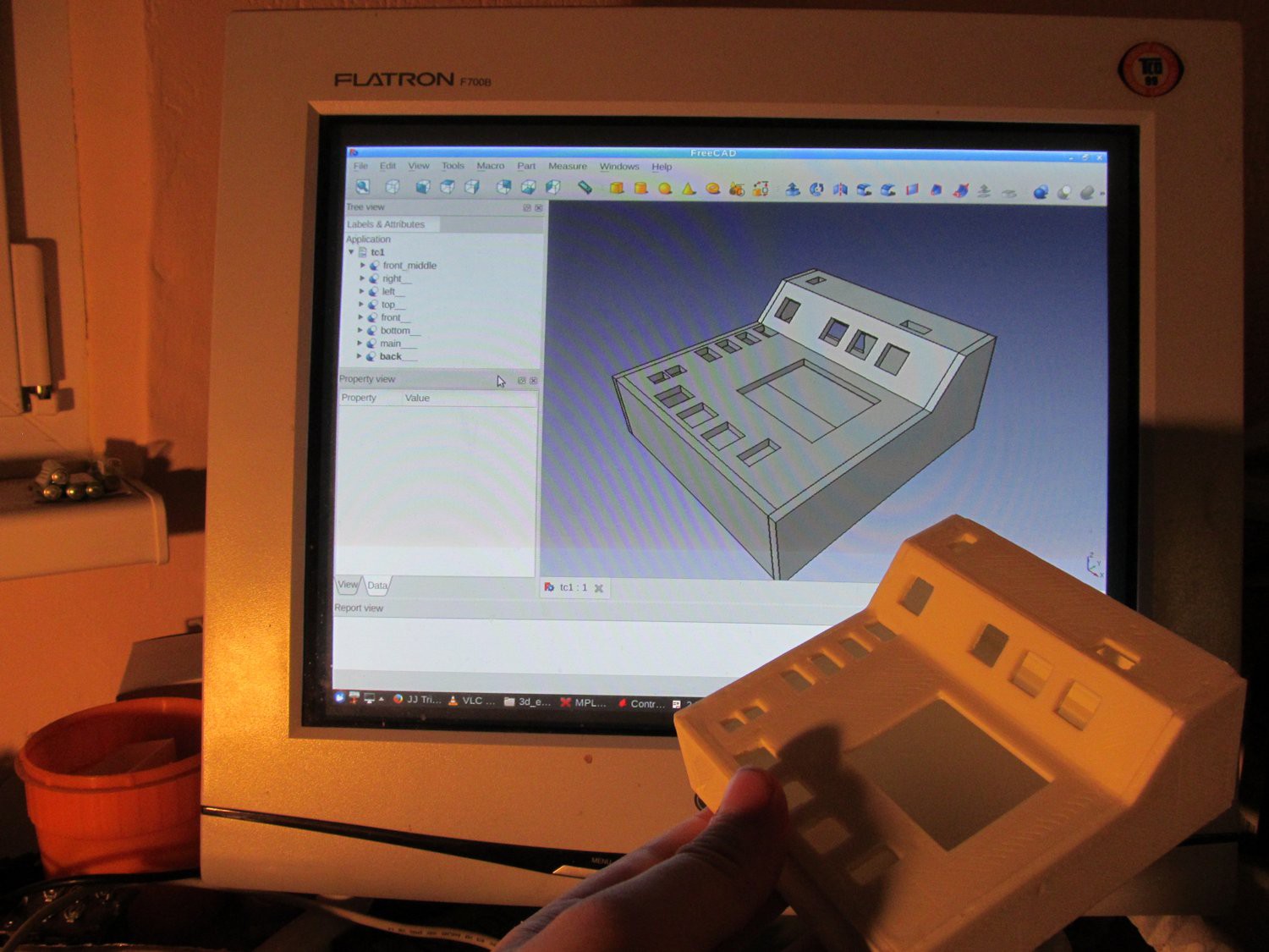 The same case, while waiting for button caps to print out.
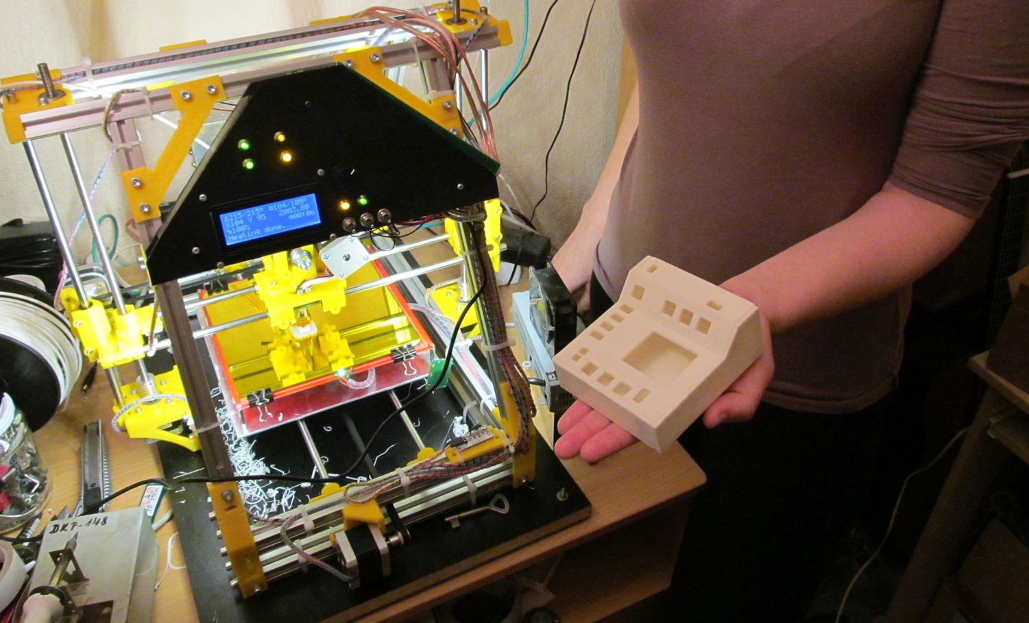 Now I'm working on firmware. Basic functionality seems to work, tomorrow I'll upload here more photos of tricorder in action, maybe some video, and design files on GitHub.
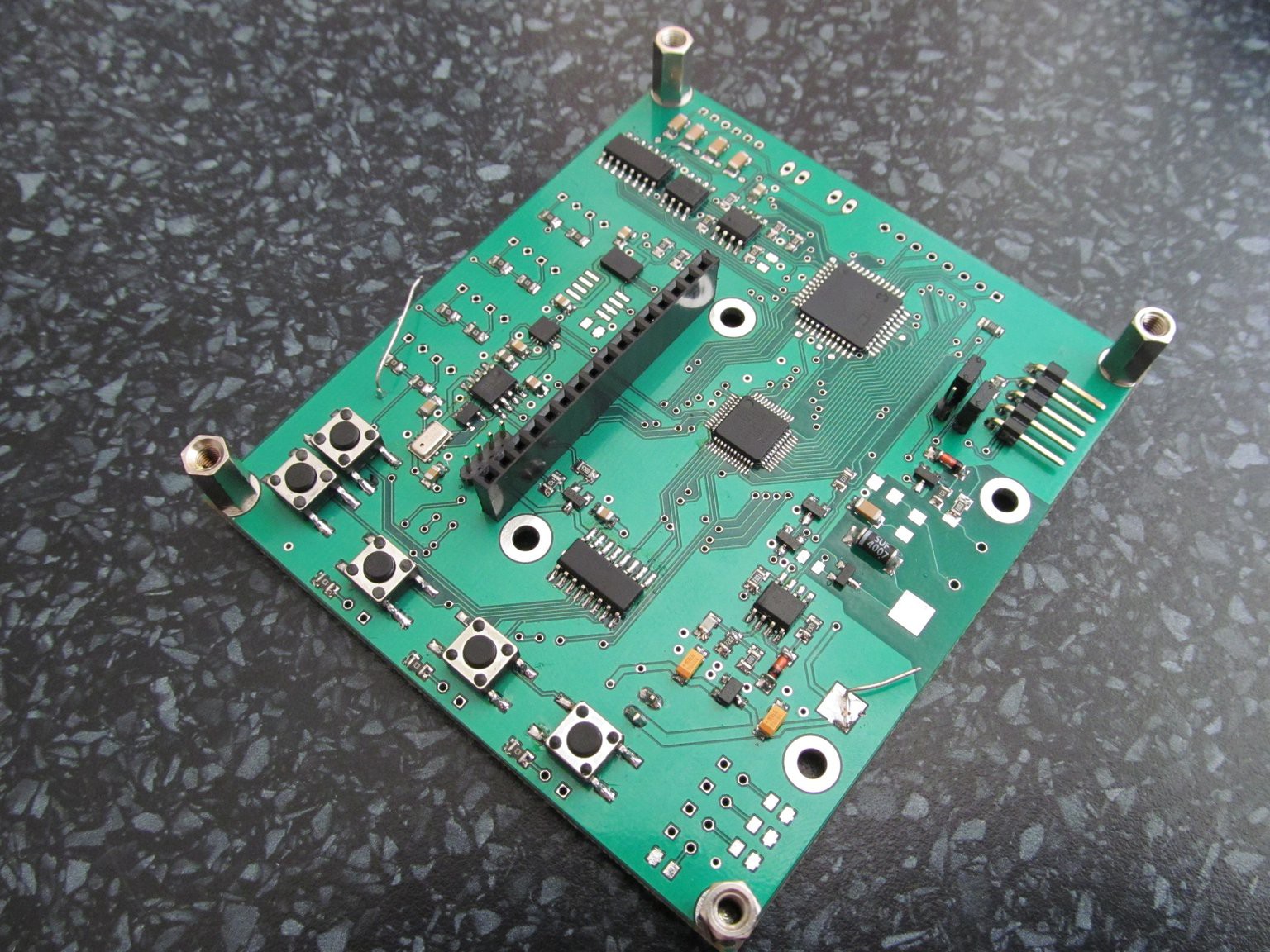
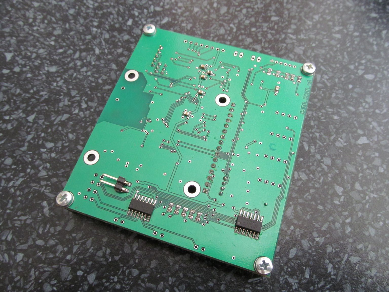
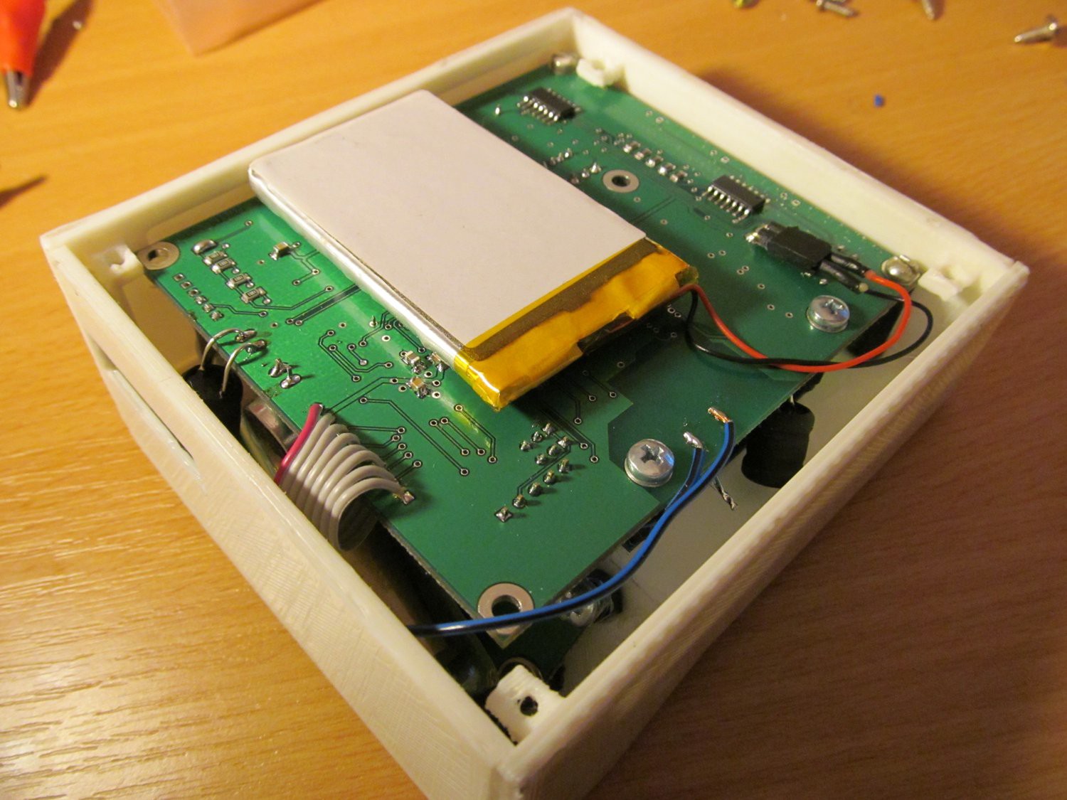
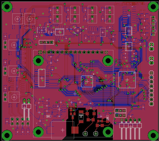
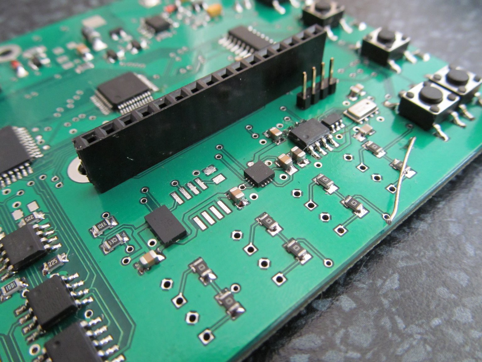 PGAs and opamps on the left side and row of I2C devices: MMA7455, unpopulated space for HIH6131, HMC5883L, 24LC64, MCP9800, MPL3115A2
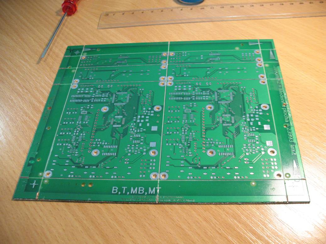
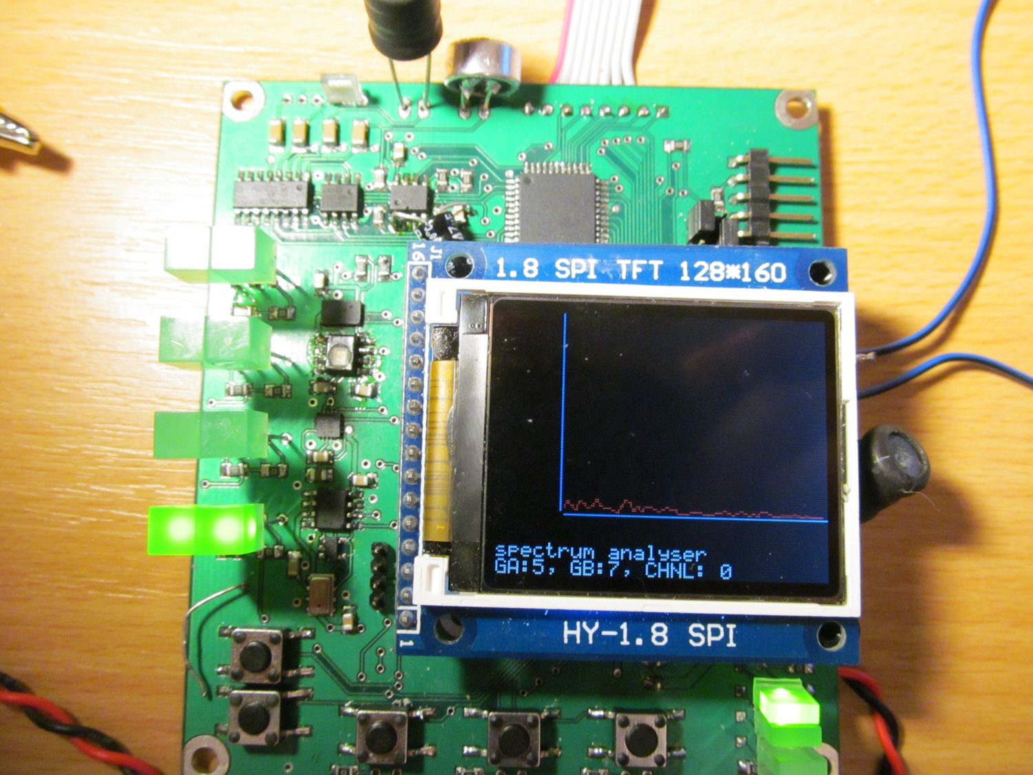
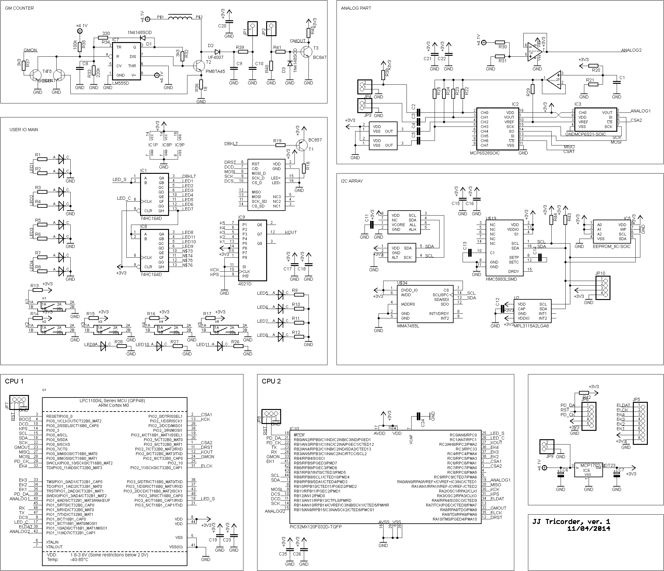 In fact, there is no rocket science involved. Just a MCU, few buttons and LEDs with serial expanders, sensors in basic application circuit and common 1,8" SPI color LCD from Ebay. For analog sensors, I designed small cascaded PGA with MCP6Sxx. Those are nice little SPI controlled PGAs. Notice the Vdd/2 source (R20/R21) with opamp as follower, biasing the output of PGA into Vdd/2 level, needed for sampling of AC signal with MCU AD input. GM counter part consists of simple 400V power source (555 circuit and associated circuitry), along with amplifier to allow direct conenction to digital input of MCU.
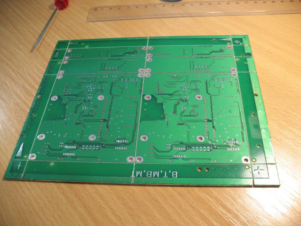
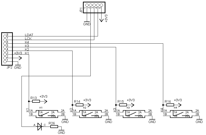 and second UI board - just IO for buttons and LEDs.
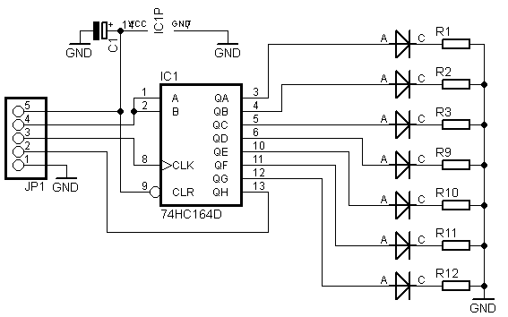


 CaptMcAllister
 Daren Schwenke
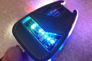
 Xasin
Xasin