 zakqwy
Six of 'em, to be precise:
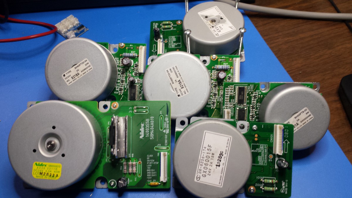
Four different types. I'll address them one by one, starting with the smallest.
Japan Servo Co. Type BH55FT8-02 / 8131A / AX050249B
24V, 2A, 8W
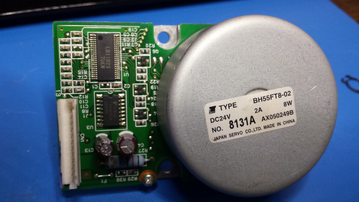
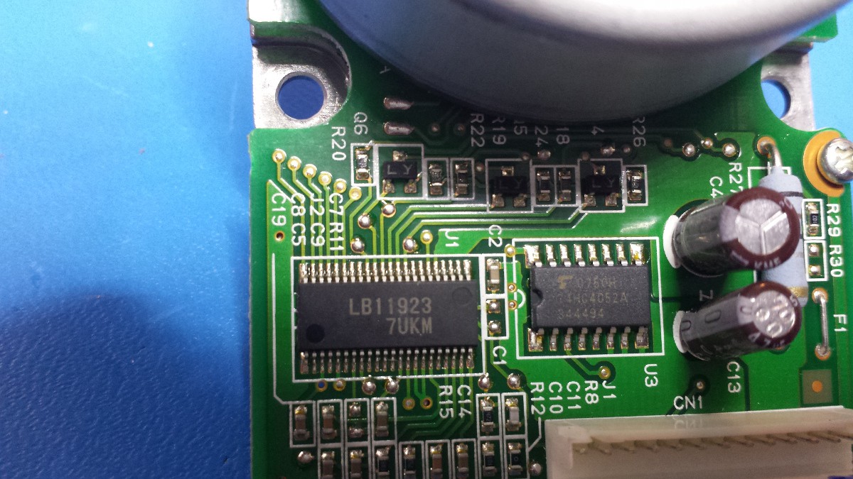
Only one of these motors. It's the only one that has two discrete SOICs, part numbers LB11923 7UKM (the 3-phase brushless motor driver IC) and 74HC4052A, which appears to be an analog mux/demux chip.
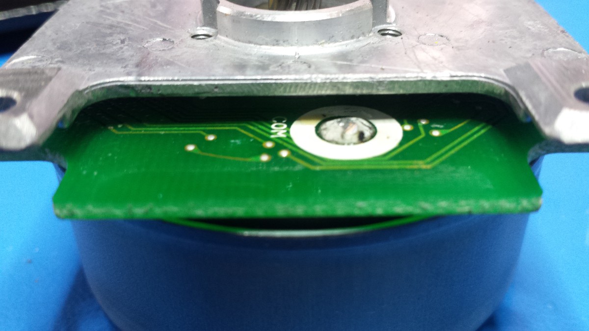
As I'll touch on later, these motors don't like getting taken apart; I can't get the rotors off without getting a bit destructive. However, these vias might be leading up to a few Hall effect sensors:
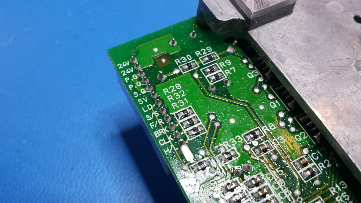
Note the beefy coil connector too--three of these spaced at ~120 degrees, as one would expect. I didn't get a shot of the underside of the board; it's got a lot of discrete components, and the white connector is labeled as follows: 24V, 24V, P.G., P.G., S.G., 5V, LD, S/S, F/R, BRK, CLK, H/L, and ENC.
Shinano Kenshi Co. DR-6236-174 / GX060015F
24V, 2A, 18W
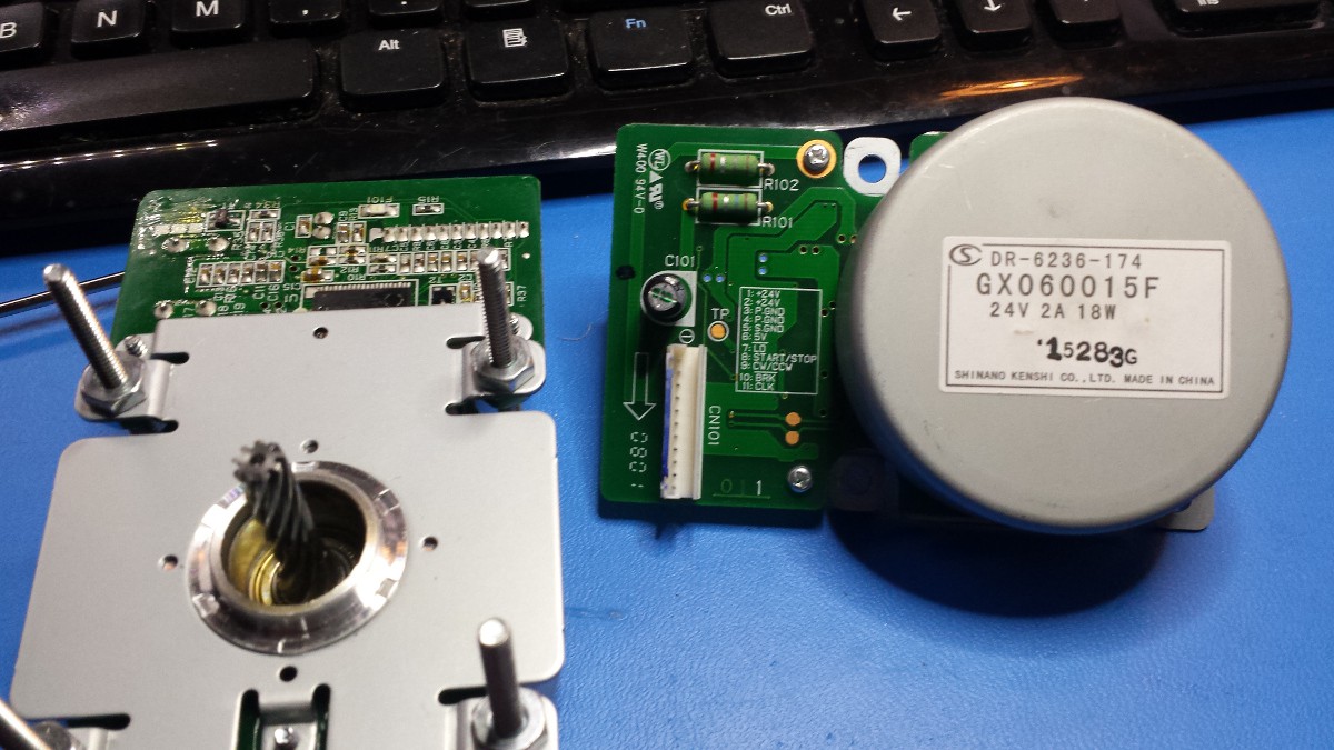
Two of these fellers. The single driver IC on one is impossible to identify; it looks like the label has been etched off or otherwise obfuscated. The other one looks like this:
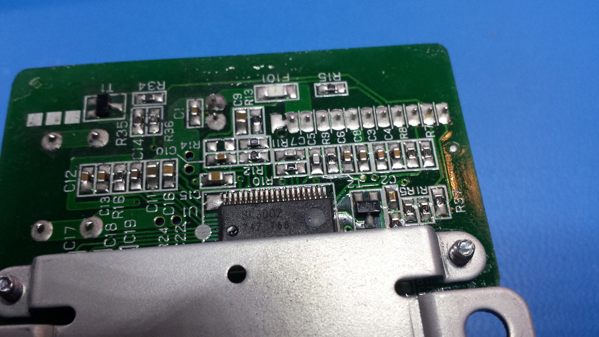
SK3002 747 T68 doesn't bring up any matches. Hell, how do you guys find datasheets online? I keep coming up with really sketchy looking sites.
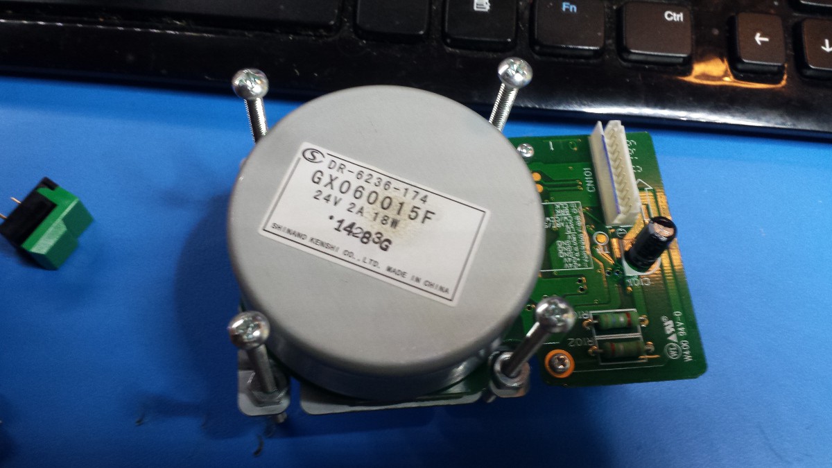
Since I had two of these (and they're smaller than the other pair) I decided to putz around with one of 'em. I used a bit of 6-32 hardware to build a little stand so the motor could rotate freely on the bench. I built up a breakout cable using one of the original connectors from the copier (thank goodness I kept the wiring harness) and fed the motor 24VDC and 5VDC; when I pulled the START/STOP pin high, the motor started twitching. It seemed to twitch once per rotation and would do this maybe 10 or so times before shutting down.
I cobbled together an Arduino driver that allowed me to send a 5V 50% duty cycle square wave to CLK; when I did this and hit the START/STOP with a HIGH signal, the motor responded by spinning at [what looked like] maybe 500-1000 RPM or so. Sending 5VDC to the CW/CCW pin, as expected, changed the direction; I think HIGH = CW, but I could have it backwards. Either way, I didn't figure out what LD or BRK did, and I didn't test CLK above 1 kHz or so.
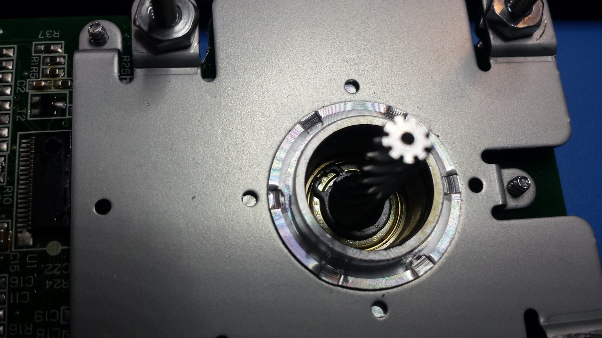
I also put a bit more effort into pulling the rotor housing off one of these units, starting by removing the label:
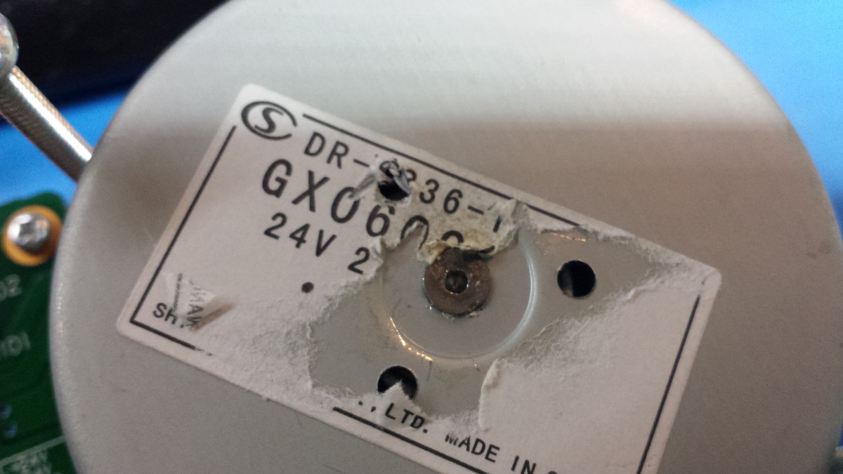
Looks like they assembled the motor and used a press to push a serious divot into the shaft, spreading it out and sealing the whole deal up. I don't think this was a malicious move to keep would-be hackers out; it's just a cheap and effective way to securely attach the rotor (which is presumably lined with magnets) to the shaft. Either way, I didn't want to drill it out so I tried the other side:
Kinda a funky looking snap ring. I don't have any fancy snap ring tools so I donned safety glasses and popped it off with a screwdriver; however, nothing seemed to come apart despite some pretty serious encouragement.
One other thing to note on these two motors:
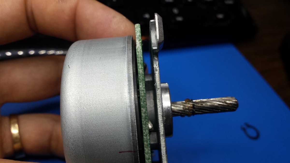
So it's pretty tough to see, but the two lines between the rotor housing and the circuit board appear to be some kind of component. There are a number of identical ones all around the circuit board, too. Maybe a bunch of Hall effect sensors? Man, that would be sweet.
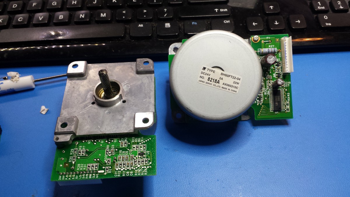
Japan Servo Co. Type BH60FT22-04 / 8218A / AX060310C
24v, 2A, 22W
Two of these guys too. Beefy, with a machined mounting bracket instead of the stamped piece on the previous pair:
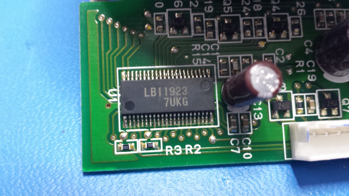
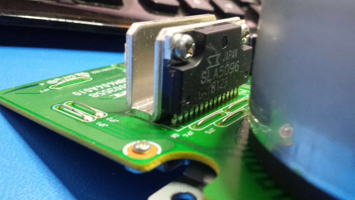
 Same driver chip as the smaller Japan Servo Co. unit, but no mux/demux visible (I suppose it could be hiding under the rotor):
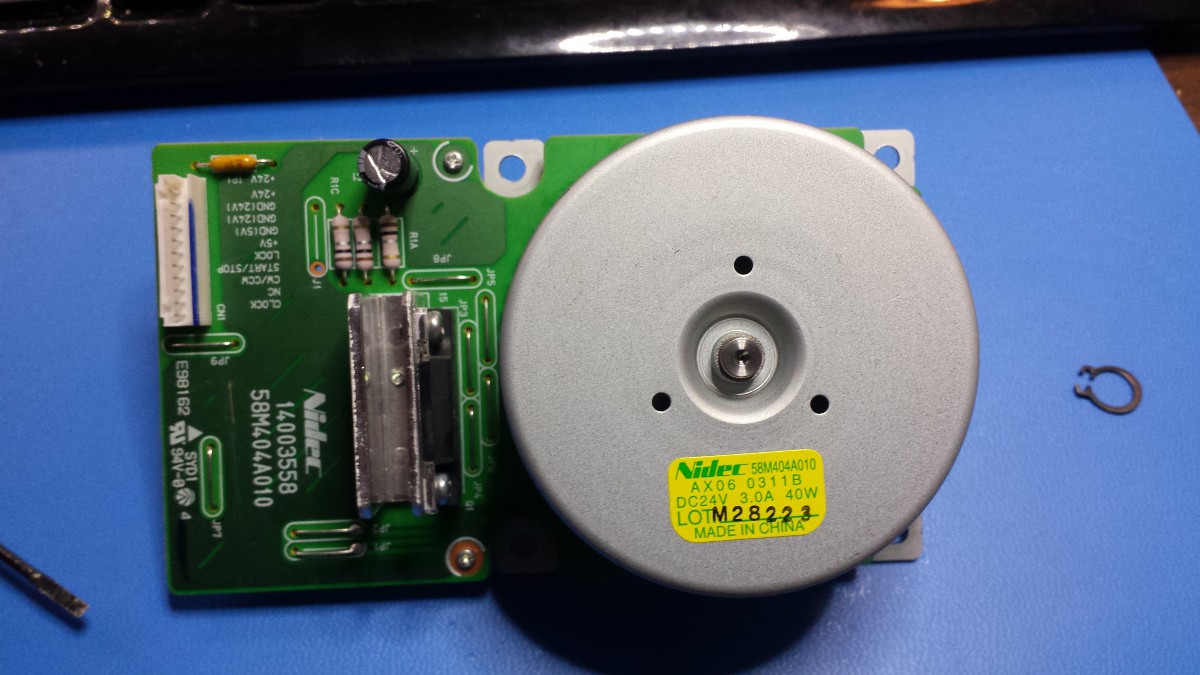
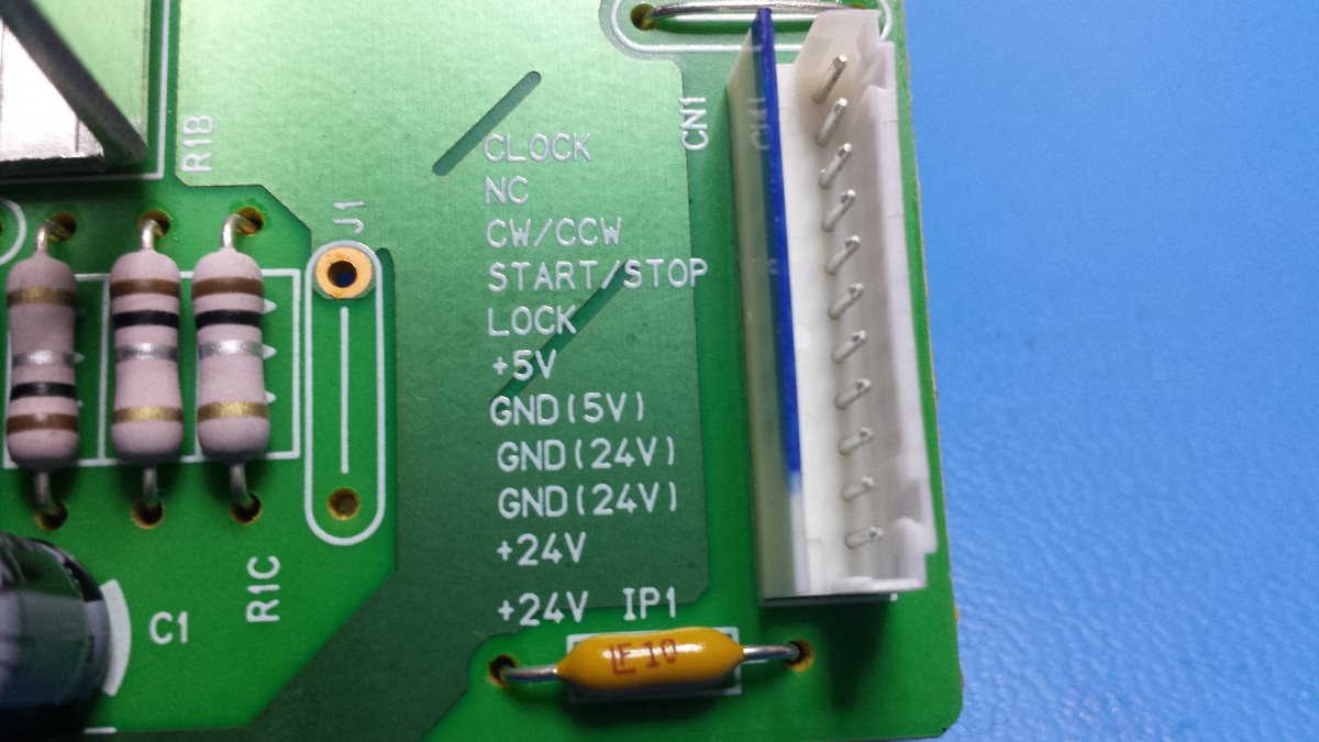
Pinout:
24V, 3A, 40W
This one is pretty beefy.
So that's where I am to date. I'd love to put together a decent driver library for these motors; something that's portable to various -Duino/etc platforms that you can feed direction, speed, acceleration, etc and know that the motor will do what it's told. @Angeliki Beyko suggested I swing by Twin Cities Maker for the Twin Cities Robotics Group meetup; I brought one of the 18W units to show and the kind folks there had a lot of great suggestions, including:
- use a polarized light source to get a better image of the ICs
- try to reassemble one of the copier's circuits, power it up, and 'scope the unknown signal channels leading to the motors
- rip one apart and figure out if it's got things like Hall effect sensors
- use the hardware but build my own driver circuit for the motors
- keep sending pulses to the motors to see how they respond
Anyone have any ideas? Who's played around with brushless copier motors?
Discussions
Become a Hackaday.io Member
Create an account to leave a comment. Already have an account? Log In.
I have some very similar motors from a Konica Minolta 7020 that I tore down. These use an SLA6012 driver. I found some relevant information to the LD pin. It likely stands for "lock detection" and is provides a signal from the driver to the controller. Below is the related content from the manual on how the pin signal is used. M1 is the motor/driver, PRDB is the main printer controller. I think these motors are intended to run at constant speed, so I think this pin is useful to detect the error state.
1) LOCK SIG (M1 −> PRDB)
A monitoring signal for the rotation of M1.
Goes [L] when M1 rotation reaches the rated speed.
[H]: Stopped, or rotating at other than rated speed.
[L]: Rotating at rated speed. (PLL: stable)
Are you sure? yes | no
also I’m guessing I’ve found other people like myself?? By that I️ mean guys that when u crack open the case of a new copy machine you get a partial erection from all the goodies inside? I’ve built a relationship with a business where I️ live (Fresno,ca) that fixes copy machines and they literally have a whole parking lot full of machines that they are going to throw away so they know me now I️ just go by whenever grab 2-3 machines whatever fits in my 4Runner and take them home and gut them so I️ have a crazy eleaborate collection of motors(reg, stepper, whatever these motors are) gears, drive belts, actuators, ect. And so my question is what do u guys do with this stuff? My end goal is to build my most intricate robot to date, I’m in college majoring in robotics I’ve built 3 other robots using audrinos(well my first one just used the chip from a $20 rc car lol) but there pretty simple I’m tryna go all out with this one. But what else can u do with this stuff I’ve tried thinking about it and come up with nothing, just thought I’d ask I’m pretty stoked I️ found this site. Thanks for hearing me out I️ realize I’m writing essays over here haha promise I’m done
Are you sure? yes | no
Can’t belive I’ve finally found info on these motors and even more crazy there’s other people that take apart copy machines for there parts lol! Anyway I’ve been searching for info on these motors forever and finally at 4:06 at night I’ve found it thank the lord. Before this all I️ could find on these motors were some weird japananse sites tryna sell them or something but I’m still pretty confused on how u guys are powering these I️ have like 10 of them but mine are slightly diff than the ones I’ve seen on here I️ can try posting pics but I’m not sure how to do that yet I️ literally joined this site after stumpling on this article and signed up cuz I️ wanted to post a comment hopefully someone can help me out a Lil not sure if this thread is super old or if it’s still active jus gotta cross my fingers hope someone gets this message lol if not gotta figure it out from ur guys posts and comment d
Are you sure? yes | no
Zoom Zoom ! - 4700 RPM - Variable PWM from Arduino ---->
https://www.youtube.com/watch?v=SMXBM76_A50
Are you sure? yes | no
BRK signal is Break, for the etched number on controller ic, dampen finger ,wipe surface, and note the surface under a magnifying glass , as the surface color changes while dampness evaporates, number etched off on the unit i have is , BD6762FV , ---->
Motor Driver IC Series for Printers Three-phase Brushless Motor pre-driver for Paper Feed Use BA6680FS, BD6761FS, BD6762FV
the data sheet is here ----> http://media.digikey.com/PDF/Data%20Sheets/Rohm%20PDFs/BA6680FS,BD6761FS,BD6762FV.pdf (note starting on page 18---->19) Servo circuit (BD6762FV)----> "Speed discriminator" AND "Speed discriminator"
on the motor interface boards 24v ground (power ground) is noted in 3 different ways (a) 24 pg, (b) 24 p gnd and gnd 24v.
for a fast wire to run ----> tie grounds together (include supply 24v grnd and 5v ground) , that would be 24 and 5v power supply grounds, and ----> on controller board 24v grnd, along with fwd (or cw/ccw), start stop, AND THEN pulse the clk input ( i used arduino , 10 - 20 ms pulses) tagged off of a blinking led as noted in the youtube video here ---->
with brk being pulled low, and cw/ccw being pulled high .... a comment for the video of 3 motors running ----> messy table , yea ----> thou its not really a rats nest of wiring if one knows which wires are which and what their function is .... just saying
some of the motor control boards will not cycle by pulsing clk, for these tie clk ans start stop together to the pwm (will not continue to run
Are you sure? yes | no
in ref to "fed the motor 24VDC and 5VDC; when I pulled the START/STOP pin high, the motor started twitching."
not successful here , what is grnd for 24v? and 5v? ----> is PG for 24 v ground ? , is SG for 5v ground? OR what?
Are you sure? yes | no
I just disassembled such a motor. All you need is a Hammer and a little hit on the shaft (in axial direction of course ;) ) I'll post the pics on my page.
Are you sure? yes | no
Hello! Nice project log! Today put my hand on one of these motors. They came from a Ricoh fotocopier. I use a PC power source (12v + 5v). Then I turn on the motor, connecting the 12v output in a 24v pin, 5v output in a 5v pin, and GND output in a GND 24 pin. So I connect the START pin (or trigger in my case) with a 5V GND (or sgnd - secondary gnd). The motor just started. If I connect the START pin with GND and CW/CCW pin, the motor runs in reverse. That's what I got for now. This driver is common in these motors: http://www.chipcatalog.com/Sanyo/LB1823.htm. I hope have helped a little. Yet make more tests.
Are you sure? yes | no
Great info--thanks! I got mine to spin both directions too, but not much beyond that. I'll look through the LB1823 datasheet when I have a chance.
Are you sure? yes | no