 WΛLLTΞCH
What is Bone Conduction?
"Bone conduction is the conduction of sound to the inner ear through the bones of the skull. Bone conduction transmission can be used with individuals with normal or impaired hearing...In use, the speaker is strapped against one of the dome-shaped bone protrusions behind the ear and the sound, which can be surprisingly clear and crisp, seems to come from inside the user's head." - Wikipedia

Essentially, bone conduction differs from conventional air conduction in that it completely bypasses the outer and middle ear including the eardrum and associated transmission bones and transmits the vibrations of sound straight to the cochlea for sensing by the auditory nerve. Anyone with an abnormality of the pinna, ear canal, ear drum, or the intricate bones of the inner ear, as is the case in many instances of impaired hearing or deafness, is able to hear the sound transmitted through bone conduction incredibly clearly with no distortion. Users with fully functional auditory systems are able to hear the bone conducted sound just as easily, and the effect is incredibly eerie as the sound or music playing seems to come from inside your own head, you are able to hear your surroundings normally in addition, and no one else can hear what you're listening to even though it sounds as if there is music playing in the room. It appears to be ghostly phantom music, hence the name.
The First Prototype
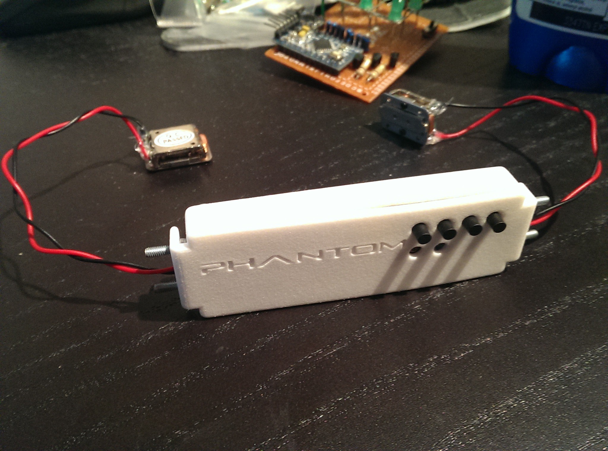
My first prototype to test the phenomenon uses a cheap bluetooth audio module from china to wirelessly receive sound from a connected device which is then passed through an Adafruit amplifier breakout before going to the bone conduction transducers. After initial tests, the volume was too quiet unamplified, so I added the amplifier behind the circuit board (which barely squeezed in) at max gain to boost the signal to drive the 1W transducers
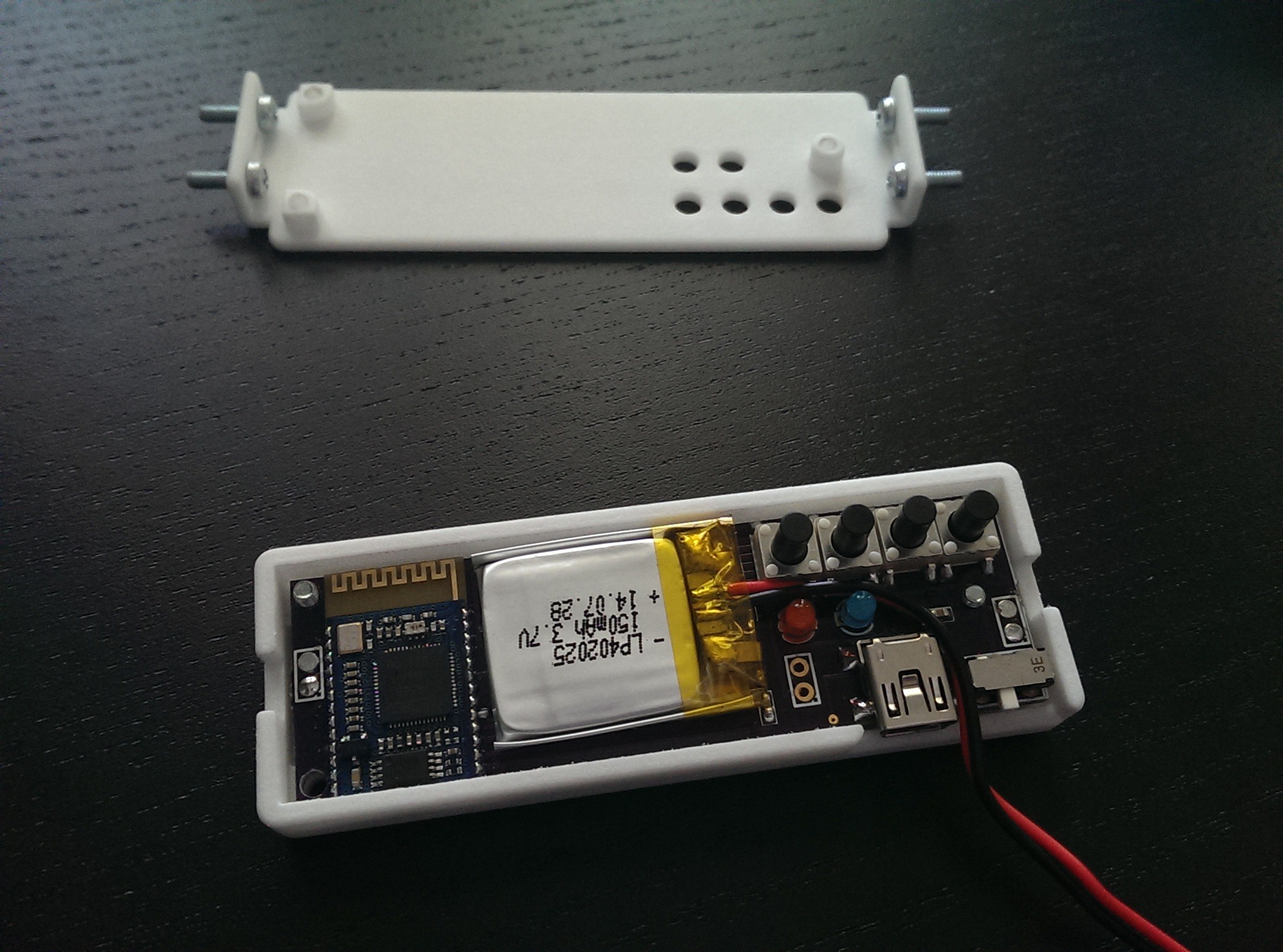
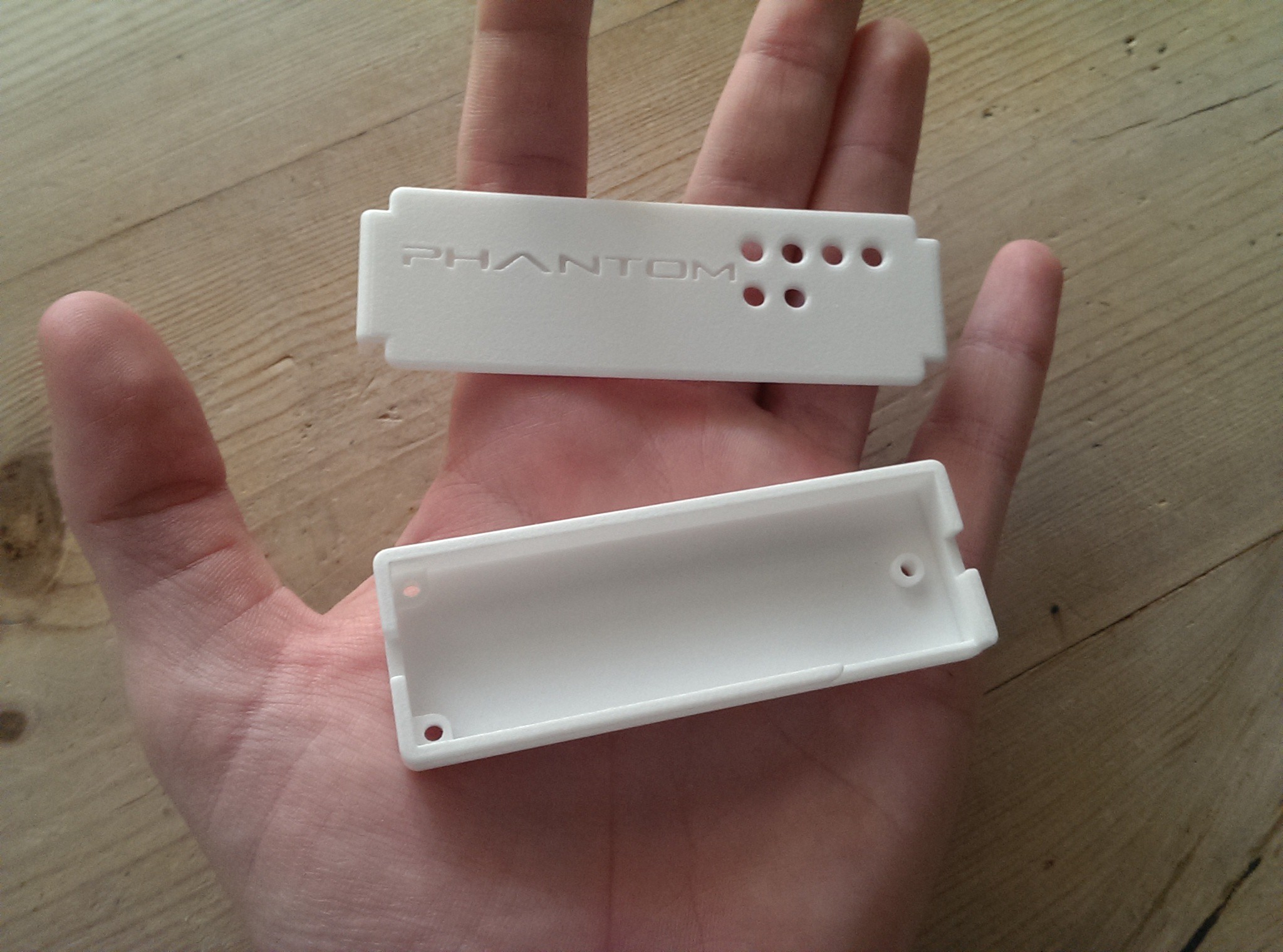
The case I designed in Autodesk 123D and is 3D printed in strong, flexible plastic by Shapeways. It has screws on each end for me to attach prototype arms that hold the transducers in different places on the skull and the PHΛNTOM logo on the front.
After some initial tweaks, it works eerily well. When it turns on, it plays some welcome tones, and then waits for a bluetooth connection. Once connected to my phone, I can control music playback with the on board play/pause, skip, and volume up and down buttons, and when I place the transducers on my ear ridges on the back of my skull, undistorted and surprisingly powerful music surrounds me in stereo, seeming to emanate from within my own head. No one else can hear a thing, and my own ears are open to listen to people talking to me and I would be aware of my surroundings on a bike for example. I named the project PHΛNTOM as the effect is ghostly and strange, as if the music was played by a phantom orchestra or a trick of the mind.
The Final PHΛNTOM 2.0 EE47 Project
From the response I've received from my first prototype, this device has incredible desirability for child and speech therapy, the deaf and hard of hearing, and certain conditions of the ear canal, auditory bones, or eardrum. So many people I have talked to are very excited about what this open-source device could do for their child/father/mother/spouse, and I am incredibly happy to use my knowledge of electronics and design to create something that started out as an experiment with sound transmission and has evolved into a life-changing device to unlock the experience of music and sound for those in desperate need of its power.

Because of this, I have decided to enter the PHΛNTOM into this year's Hackaday Prize competition with the goal of creating something that matters and a grand prize of a comercial spaceflight, and I think this project really does matter. I entered my smart watch last year and was a quarter finalist (top 50 of 800), you can see that project here: (https://hackaday.io/project/1348-wlltch-oled-btle-smart-watch-v61)

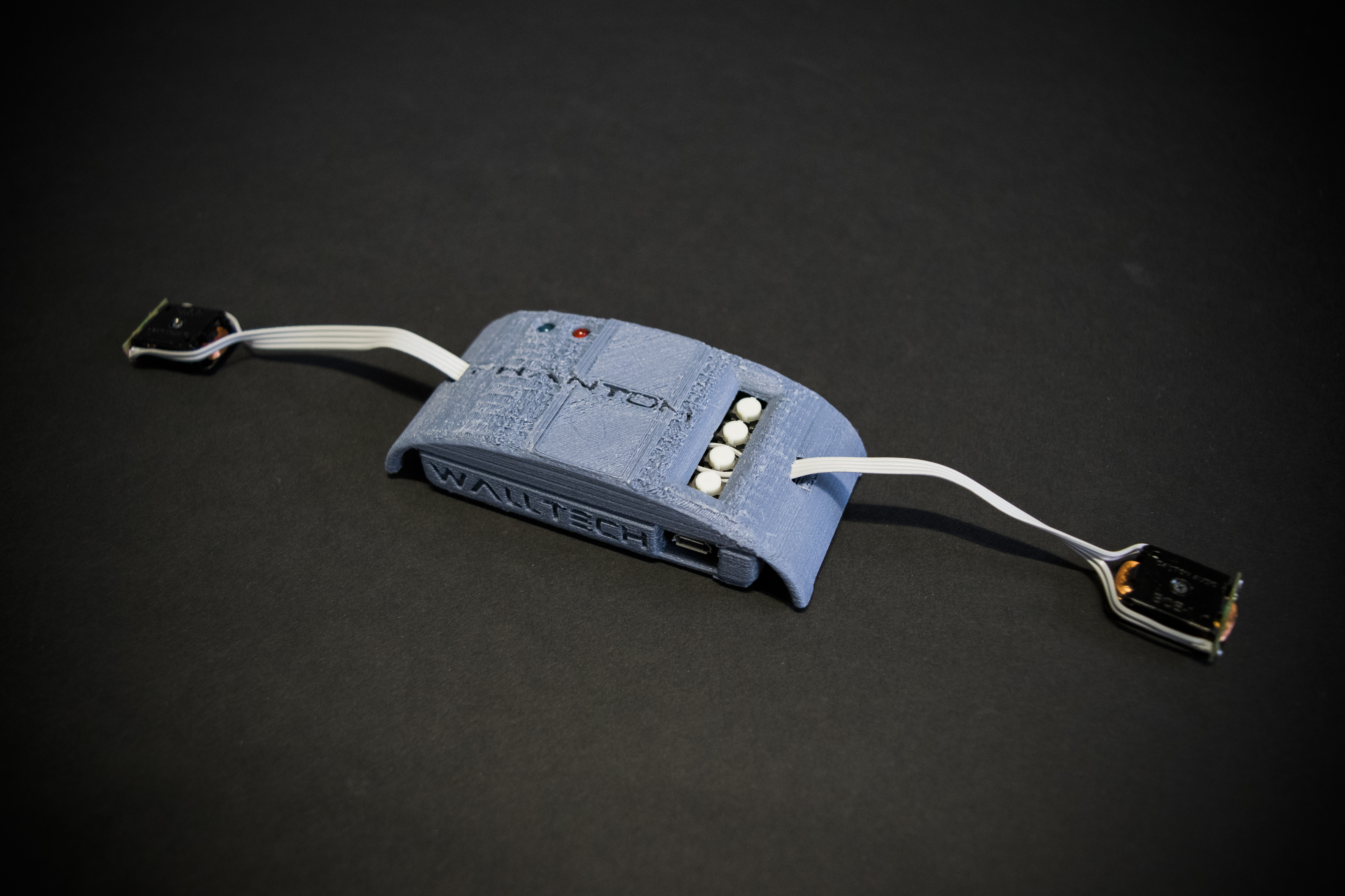
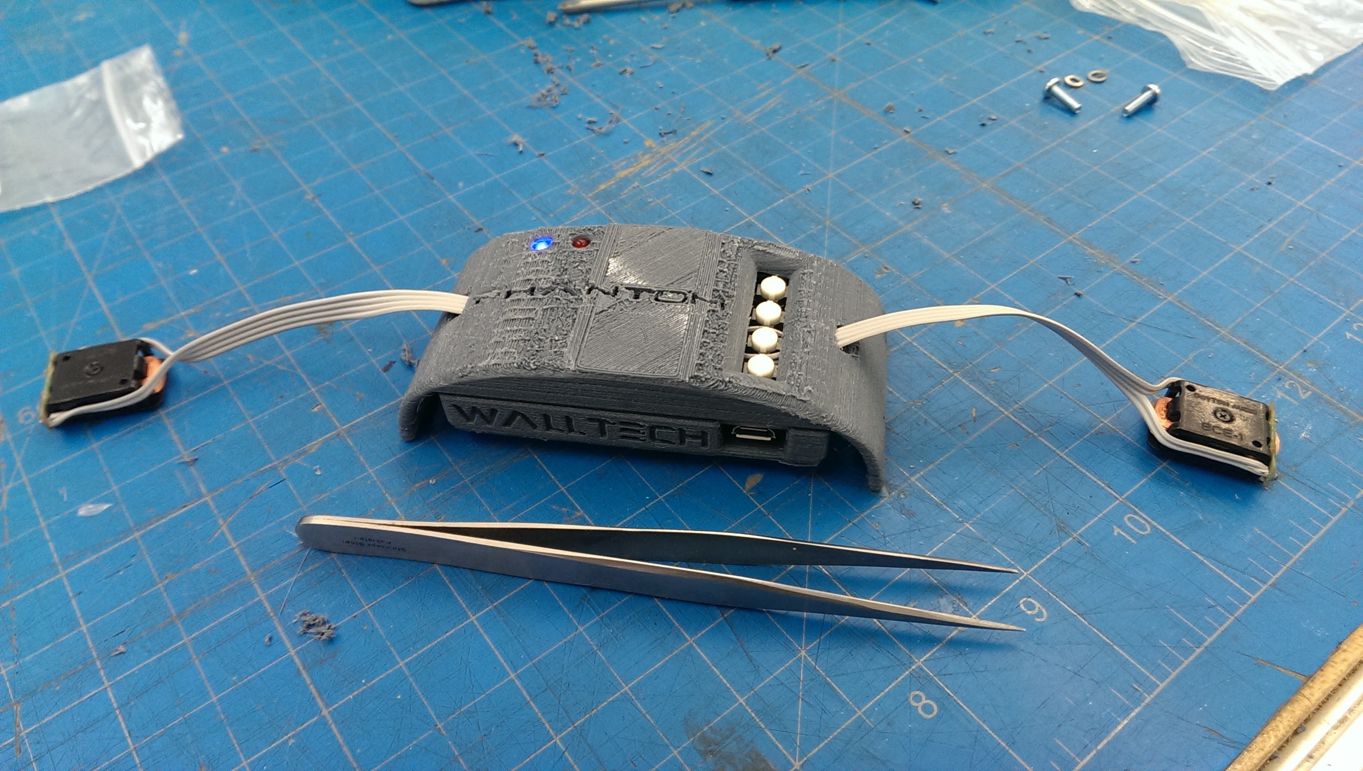
This new version of the bluetooth bone-conduction headset concept adds higher-quality components, better aesthetic design, a bigger battery, and more features. v2.0 has stereo microphones to receive bluetooth phone calls and add adaptive-volume hearing-aid functionality to the device. The four push buttons control volume up, play/pause, skip, and volume down functions in order from top to bottom. An internal amplifier boosts the volume to the transducers, an issue with the last prototype. The internal bluetooth audio module is a Microchip RN52, a VERY nice improvement over the $5 generic module from china in v1.0. Range should be increased as well as audio quality and the addition of microphone capability and status led feedback. The mounting system has also been improved from a solid grasping arm type design to an adjustable strap worn like a headband. Several people have asked for a 3.5mm audio jack to be included as an optional input, and at the scale of the internals of this device and the nature of its mounting, a wired connection would be impractical and against its intended use. If people really want one, I'll think about adding it into a future revision.
Design
Verplank Diagram
State Diagram

PCB
I designed the PCB with Fritzing even though I wanted to upgrade my software this summer as it's quick, easy, familiar, and more than capable for this project.

(yes, that's Shia Labeouf motivating on the back of the pcb, if you're saying to yourself, "I can't design a PCB," all he has to say to you is YES YOU CAN! JUST DO IT! DON'T LET YOUR DREAMS BE DREAMS, NOTHING IS IMPOSSIBLE!)
3D Printed Case
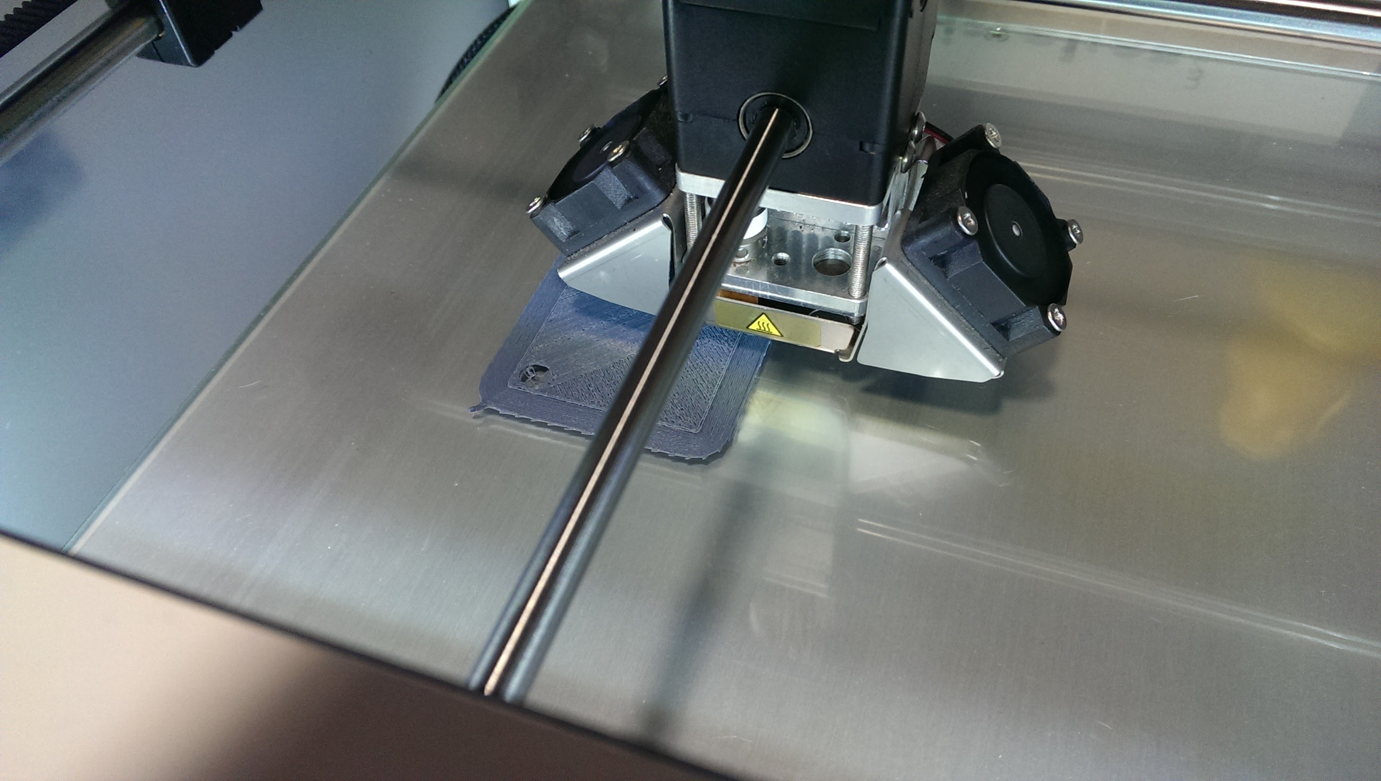
Once the PCB was complete, I used Autodesk 123D Design to 3D model a case to enclose the circuit board and components. The case will slide onto an adjustable or elastic band that will secure the device and transducers to the back of the user's head. The new shape is much more appealing than the last design, and the mounting style is simpler, more adjustable, and more user-friendly. I will eventually have this case printed in high-quality glossy white from Shapeways, but PRL Ultimake turned out to be perfect as a test of the case design (also costed $1.25 for over 6 hours of printing). The main body of the case is 40x70x20mm.

PCB Pickup and Parts
PCBs
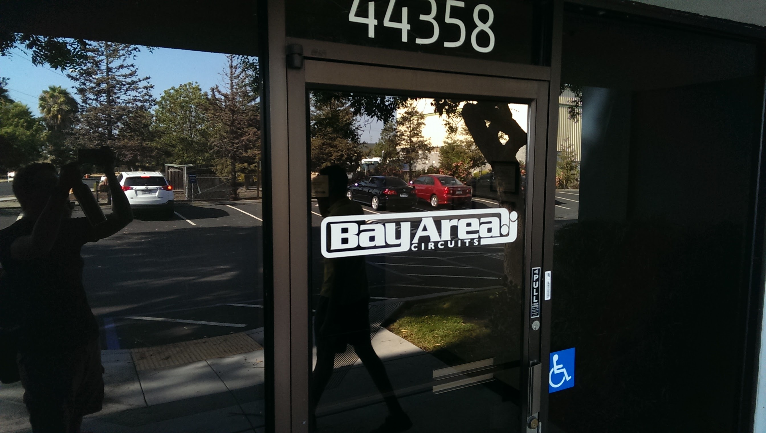
To pick up my PCBs that were perfectly crafted (in 2 days for free) by Bay Area Circuits in Fremont, CA, about an hour away from Stanford, I toured the facility (cheers Brian) and got to see the whole production process as well as the incredible machines that make it happen. It was an amazing tour, and I'll release photos as they are approved by PR for the public.
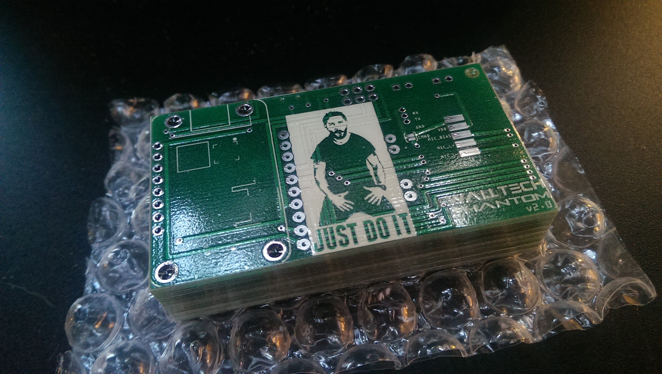
Finished PCBs: (JUST DO IT!)
Parts list
Here are the parts I used for this project. Purchased from Mouser.com with my prize money from my smart watch entered in last year's Hackaday Prize competition.

Once everything had arrived (just in time) I assembled the PHΛNTOM in the PRL!
Final Assembly
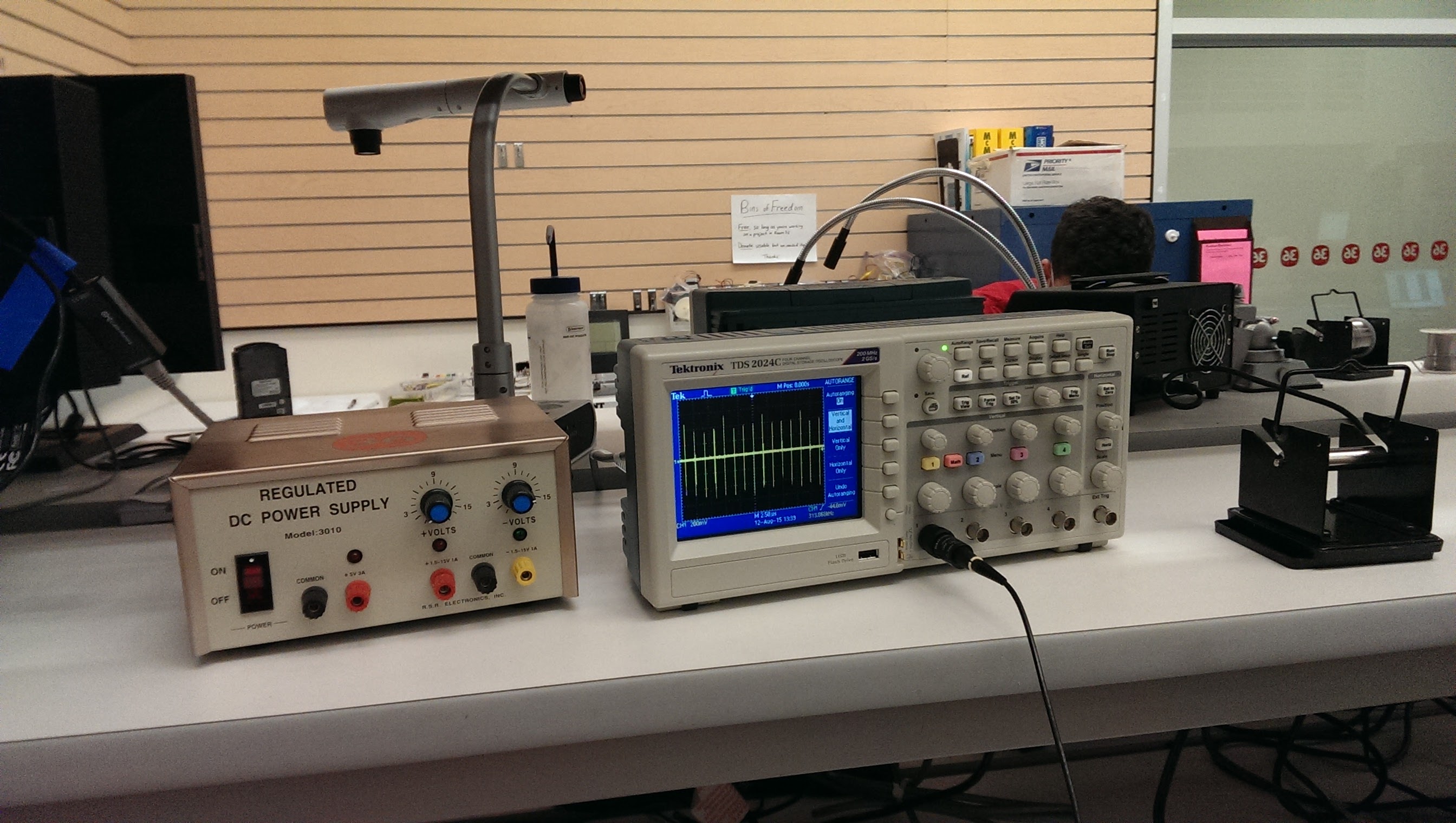
In order to assemble the PHΛNTOM, I first had to modify the Adafruit PowerBoost 500 charger from outputting 5v to outputting 3.3v. Upon looking at the datasheet for the TPS61090 boost converter from TI, I calculated that a 1.13MΩ resistor in the place of the current 1.87MΩ voltage output programming resistor would modify the board to output ~3.3v. I checked the board's output. 3.5v. In spec. When that was done, I could assemble my circuit, and everything worked first time! I tested the output with the lab oscilloscope before wiring the transducers and the signal appeared as expected.

After the electronics were complete and working, I had to connect a serial programmer to the RN-52 bluetooth module in order to program the function buttons and set a custom name and passcode. I followed the instructions on the module's guide on Sparkfun (https://learn.sparkfun.com/tutorials/rn-52-bluetooth-hookup-guide) and designed the serial lines and programming enable connection in my PCB.

With the commands entered and the buttons/custom name working I 3D printed the case on the PRL's Ultimaker 2 for 6 hours and the price of $1.25!


After I cleaned up the support material as best I could, I placed a Samsung NFC tag under the lid of the case and configured it with NFC Tools, an app on my phone, to automatically request a bluetooth connection from a device that scans it. After the tag was in place and scanning, I tapped the mounting holes in the case with 4-40 screws, wired the transducers through their slots in the sides of the case, and screwed the case together. All the dimensions for the case were correct and again the design worked first time! PHΛNTOM complete!
Working Project!
It works! This project has been a dream in its conception and realization at Stanford. My PCB worked first try, the case did too, so did the BT config, it was magic. The great people of EE47, Professor David Sirkin and the TAs, Akshay Trikha and Joe Aubuchon, best lab lads ever, Room 36 (The Stanford Product Realization Lab makerspace), Adafruit for being awesome (as usual), Microchip for making the best BT audio module ever, Bay Area Circuits for the invitation to tour their facility and donating 8 fabulous PCBs from their latest production tech, and all those who's floored jaws in wonder from a little box on the back of their head kept me so passionate about this project, I thank you. I hope the Hackaday Prize judges like it as much as I do! Here it is in all its glory:
Future Improvements
- Strengthen the strap mounts on the sides of the case
- Find a strap that will fit the device to the user's head
- Model transducer mounts for the strap
- Print it in gloss white plastic from Shapeways
- Wire the microphones and test their functionality
- Mount the microphones on the strap
Licenses

All WΛLLTΞCH hardware and software by WΛLLTΞCH Electronics is licensed under aCreative Commons Attribution-NonCommercial-ShareAlike 4.0 International License.
All WΛLLTΞCH images and logos by WΛLLTΞCH Electronics are licensed under a Creative Commons Attribution-NonCommercial-NoDerivatives 4.0 International License.