 Marc-O.
The power supply can be divided in 3 main parts:
- Current sense
- Voltage regulator
- Voltage adjustment and inputs
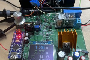
The current sense consists in a 1Ohm resistor on the high-side and an amplifier. The output of the amplifier is 1mV/mA. This value will then be compared to the maximum current set by the user.
The Voltage regulator is a typical usage of a LM317 (I used a LM338 because it was almost the same price and that the only difference that I know of is the maximum current). The output of the regulator is always 1.25V above the adjustment pin. That's why I added a -1.25V rail in the hope of getting as close as possible to the 0V output. The LM338 as a minimum load requirement. A constant current source (LM334) is used to have a 2mA load. I also added a couple protection diodes.
I'm not sure yet how I will do the inputs. Currently, I use simple pots but they are inaccurate. I kept that out the the design for now but the interface is simple. Vset should be between 0 and 12V and Iset between 0 and whatever the max current is.
The voltage input needs to be offset to bring it in the range -1.25 to 10.75V needed by the voltage regulator (I used a voltage reference LM4041 to do that, maybe there is a simpler way but I don't know it).
The current limit input is compared with the current sensed. When the current sensed is greater than the one set, the voltage input gets bypassed and the output voltage reduces.


 Bud Bennett
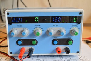
 w_k_fay
 Krists
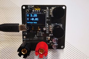
 CentyLab
FYI: https://hackaday.io/project/19078-adjustable-linear-bench-supply-in-1k
AVR controlling the output voltage with a high res. DAC out of discrete. Additional DAC output can be added for controlling current limits. I prefer external feedback loop (vs firmware) as they can be a lot faster.