 Mike Rigsby
To make the module stand requires power and control. Here's a schematic of the power components.
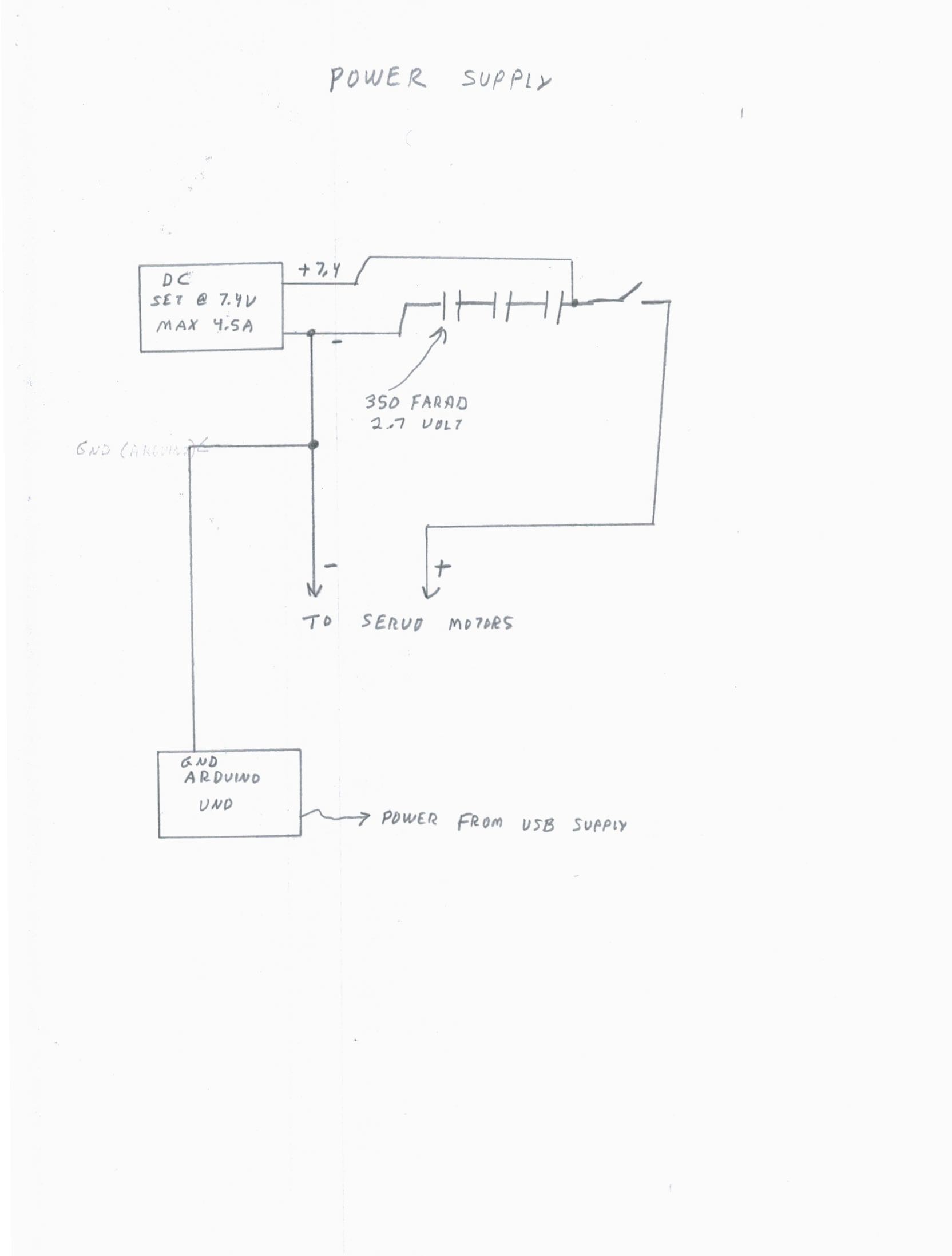
Let's look at the physical wiring. I connected the + and - power blocks using number 18 stranded wire.
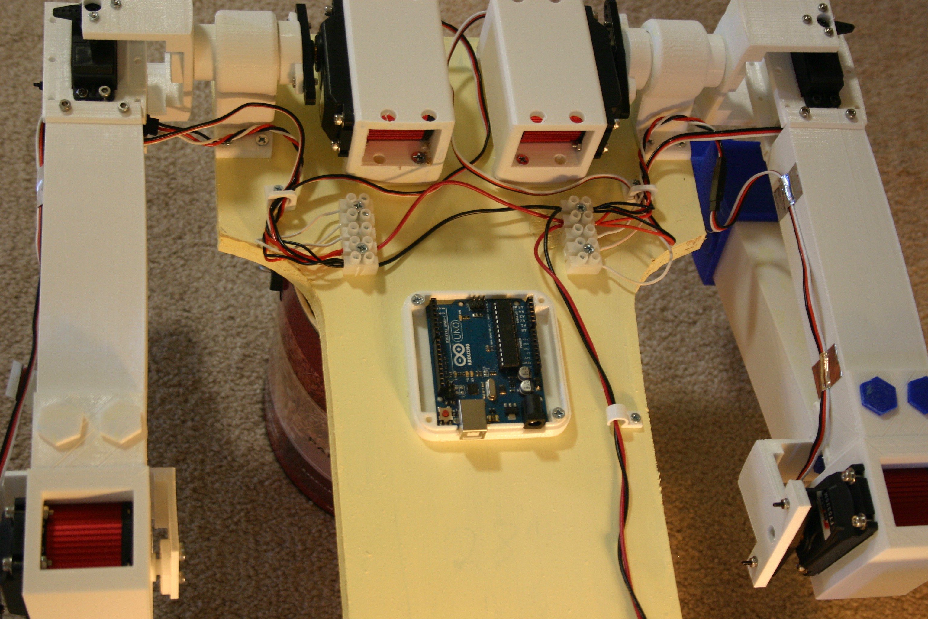
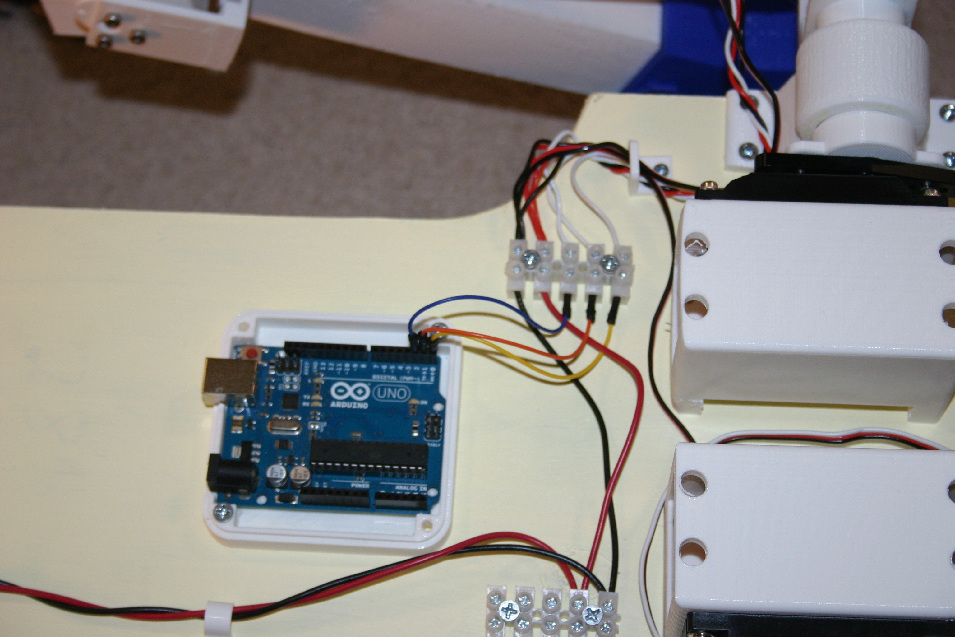
I added an Arduino Uno to control the servo motors.
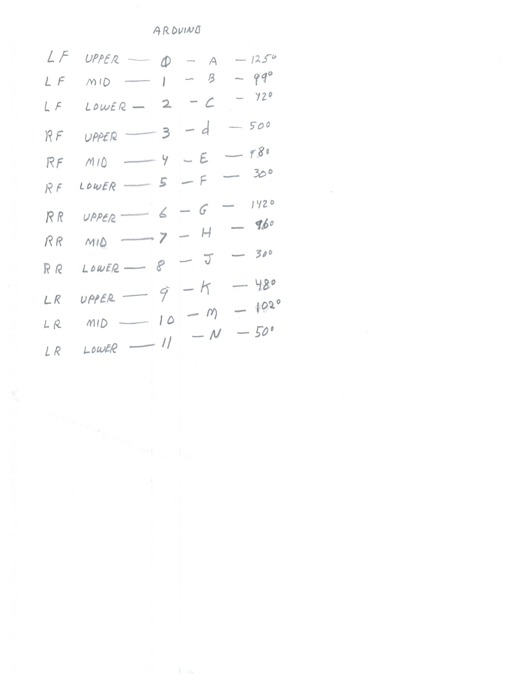
Pins 0 through 11 are connected as follows:
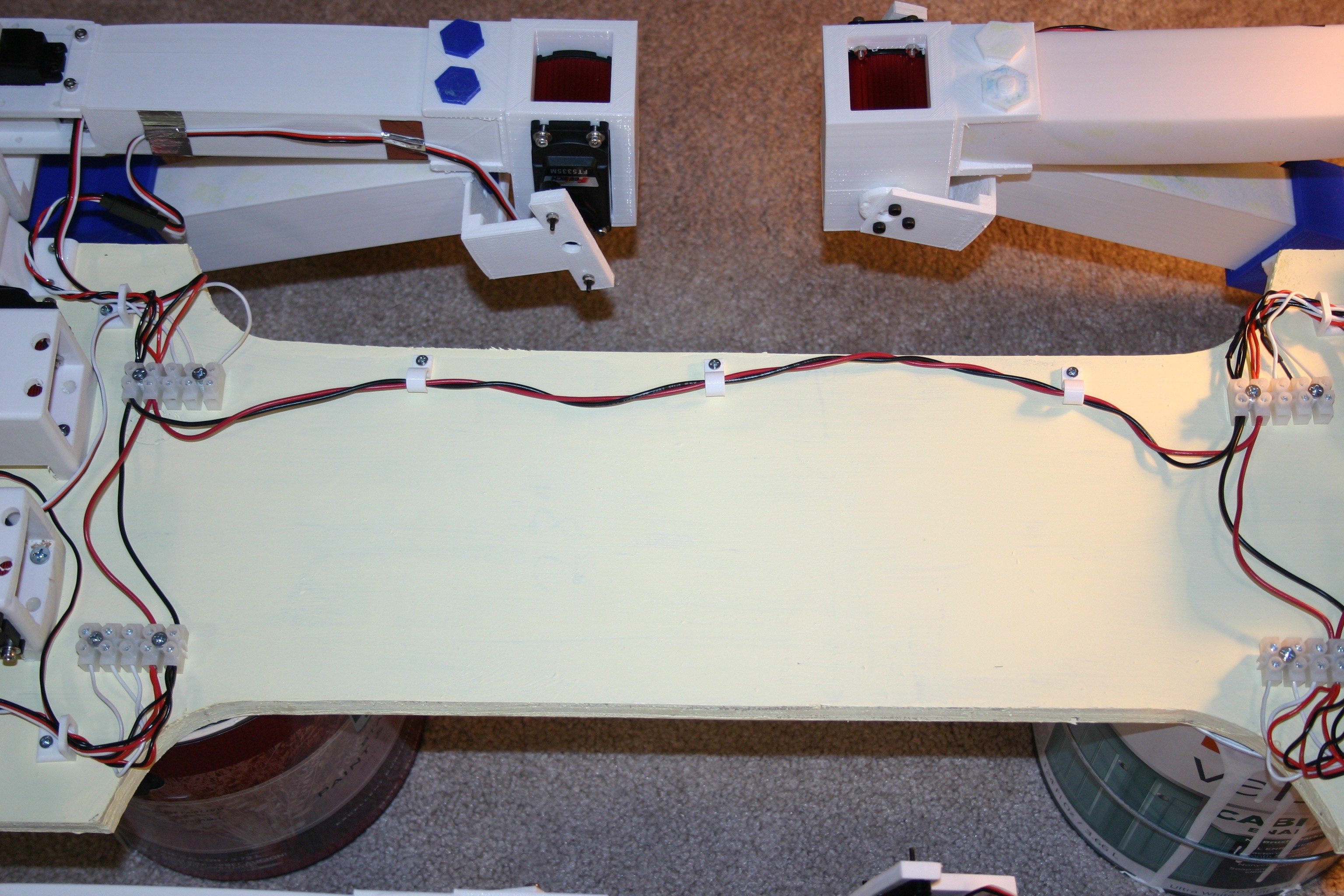
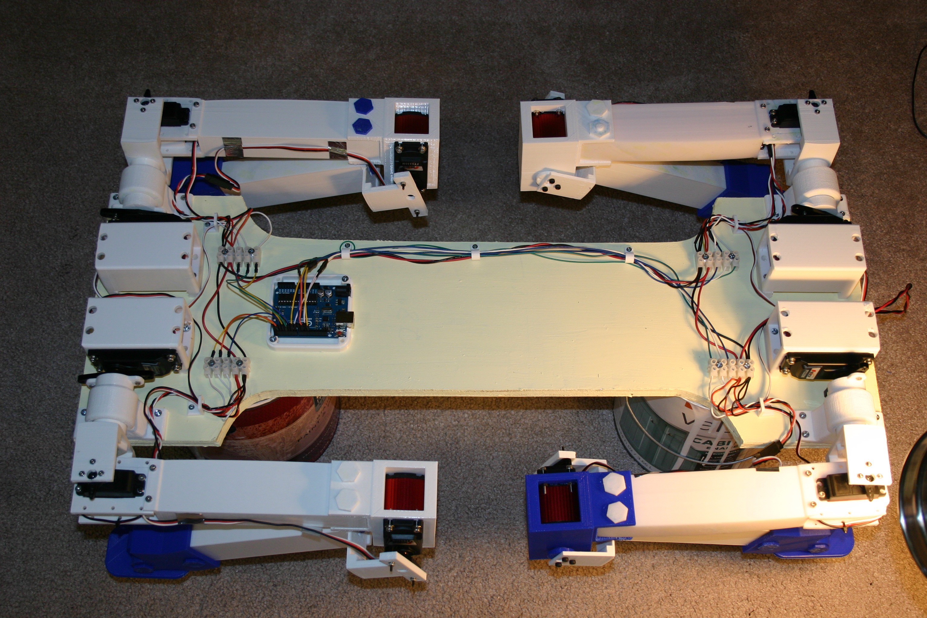
A top view of the connected wiring is shown below.
The starting position for the servo motors on the legs is shown below.

Because each spline on a servo shaft/horn represents about 15 degrees, the servo motors must be operated until a satisfactory position is achieved and that value should be recorded.
The .ino Arduino sketch for standing/sitting on this site as module test 0524.
Here's the standing routine.
Discussions
Become a Hackaday.io Member
Create an account to leave a comment. Already have an account? Log In.
You are correct--I really haven't worked out the onboard power supply yet.
Are you sure? yes | no
Very neat cabling! I always have problems with that. One note, though — I would connect the capacitors after the switch. They always have some leakage current, and might drain your battery if left switched off for a long time.
Are you sure? yes | no