As I’ve been developing this satellite tracking console, the goal has been to create a really unique piece of hardware that does useful work. The fact that it’s built up from a very eclectic collection of parts is pretty important to the aesthetic, so when I started thinking about doing a map-based display of satellite location, I had to do some hard thinking on what to use.
When it comes to Cold War-era display hardware, I first considered going purely electromechanical. This type of map can be seen in the James Bond movie, “The Spy Who Loved Me”. In the climactic scene, there’s a huge semi-transparent globe with lights underneath that designate the locations of the hijacked submarines and the nukes they launch. Major retrocool aesthetic to be had there, no doubt.
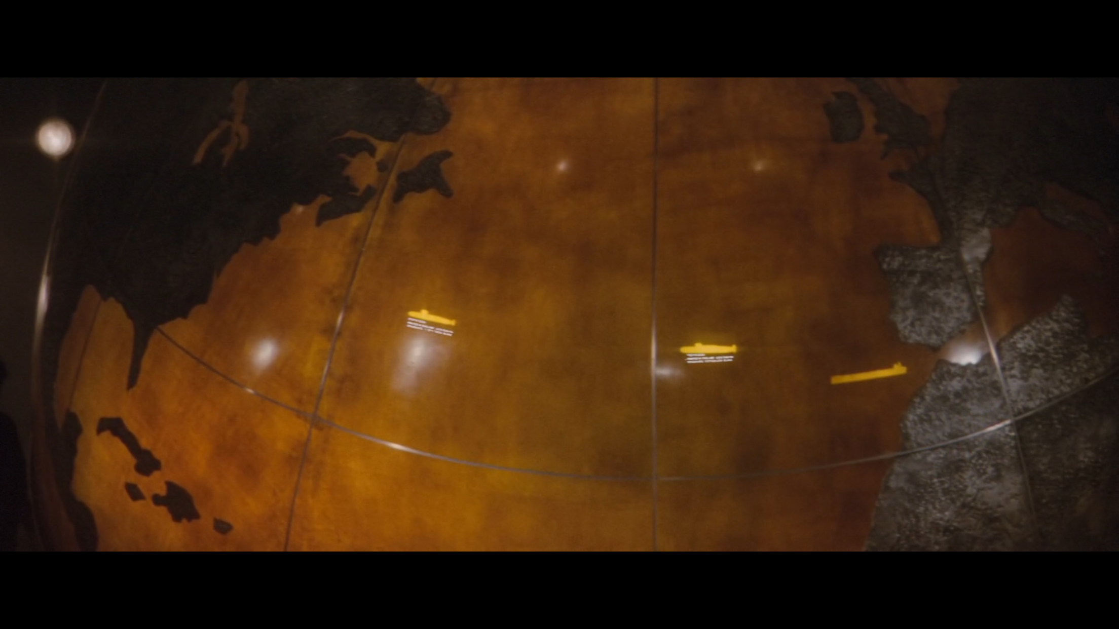
Stromberg did not deserve such a legit map.
Looking at how I could accomplish this, I considered using a piece of plexiglass that I would mask off and etch latitude and longitude squares into. This panel would cover a simple X-Y robot that could position a glowing LED anywhere underneath that panel, which could fade on and off in a convincing fashion to show the location of the selected satellite.
While the effect would undoubtedly be fun to watch, the electromechanical technique had a major shortcoming. There was no way to easily show the curved line showing the future track of the satellite. This feature is one of the coolest things about satellite tracking maps, and I didn't really want to give it up. I considered trying to build the ability to form bezier curves out of a light pipe into the X-Y bot, but that was starting to get pretty complicated. I also thought about using a galvanometer and laser to trace the curve onto the panel at high speed, but I wasn’t sure about dumping that 80s aesthetic right on top of my 60s-style map.
Since it was starting to become obvious that the display would most likely be purely electronic in nature, I started thinking about CRT-based displays. One of the first things that came to mind was to hack a vector board from an old Atari arcade game (like say, Asteroids) into the system and use that with some DACs hooked into the transputer hardware. There’s a lot that I totally loved about that idea, especially considering how much I adore those old Atari vector games, but there was another factor that played into my eventual decision: my long-standing desire to create something useful with 6502 assembly.

The MOS Technologies 6502 is one of the most ubiquitous microprocessors of the 20th Century, and can be found everywhere from embedded systems to the original Nintendo Entertainment System. In fact, 6502-based hardware was responsible for some of the coolest consumer electronics of the Cold War era. Here’s a short, not all-inclusive list of 6502 love (including variants such as the 6507 and 6510):
- The aforementioned Nintendo Entertainment System.
- Commodore 64, best selling computer of all time.
- Commodore VIC-20, predecessor to the 64.
- Commodore PET, predecessor to the VIC-20.
- Commodore 1541 Floppy Drive. Commodore really loved the 6502!
- Atari 2600.
- Atari 800.
- Tamagotchi. 6502 in your pocket!
- BBC Micro. Even the Brits loved the 6502.
- Bender Bending Rodriguez, bending robot. Shown to have a 6502 in his noggin in the Futurama episode, “Fry and the Slurm Factory” :)
- and last, but certainly not least, the Apple I and II. That’s right, the chip responsible for computing whether your beloved Mario fell into the abyss is the same one responsible for informing you of your death from dysentery.
When it came to choosing a 6502-based platform to assimilate as part of this beast of a project, it was kind of hard to find one that fit the ‘theme’ of exotic, industrial-grade hardware. That list above? Full of gaming systems and kiddie stuff. None of them too rare, either.
The whole 6502 idea might have actually stopped there, were it not for the fact that Ivan much preferred industrial espionage to actual engineering. There was hardly a single piece of commodity silicon that the Soviets didn’t rip off, and when it came to building computers around them they could hardly be bothered to design those completely from scratch, either. And that’s how the Pravetz 8-bit computers came to be.
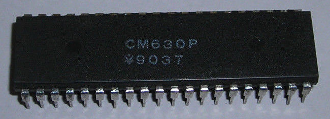
Those crazy Soviets: in ur fabs, ganking ur masks.
These rare (in Western terms), Bulgarian masterpieces of ‘engineering’ are compatible with (read: copies of) the Apple II, and that makes them both exotic enough to qualify for a place in this project and straightforward enough to implement an awesome map display upon. The difficulty level of this whole project is already through the roof, and to be honest I was looking forward to getting down with one of the most well-documented platforms on the planet. Even better, there are all sorts of Apple II emulators out there that I can use for development, which lets me both develop while traveling (one of my favorite ways to pass time while waiting to get to the next place) and also severely reduces my assemble/reboot/run cycle time.
Having chosen a platform, it’s been pretty fun to develop the map display from there. My general roadmap for this subsystem is as follows:
- Investigate Apple II display modes and determine the most suitable.
- Choose a 6502 assembler.
- Create a compatible background map in bitmap format.
- Write assembly code to display said map.
- Create an Apple II expansion card that can talk to the transputer subsystem.
- Write expansion card driver code to receive satellite position and metadata.
- Write assembly code to blit a sprite representing satellite location.
- Combine map bitmap, transputer interface driver, map display code, and satellite position display code into a single ROM image.
- Burn ROM image to EPROM.
- Hope it all works!
I’m currently in the middle of items 4 and 5. For display mode, it’s double hires all the way, especially considering I prefer a monochrome display. Unfortunately, this is also the most difficult display mode to implement in assembly, given how it interleaves the pixels between completely disparate parts of the Apple II memory map. The common way to deal with images on the Apple II and many other 8-bit-era platforms is that the BSAVE routine ‘pre-interleaves’ this data, letting one simply BLOAD the image, presumably because speed in most situations is more important at time of loading than saving. However, considering that I’m only loading the image once in the beginning, I’d rather sacrifice speed for compatibility and use a standard .BMP file.
About that background map. You wouldn’t believe what a nightmare it is to get Photoshop to output a non-anti-aliased, black-and-white bitmap, given a vector input image! That whole workflow was a complete pain in my ass. First I had to find a fairly clean vector image showing continent outlines. That was harder than one might think! Then I had to do some tedious cleanup on that image, getting rid of text and some boundary lines that I didn’t really care about (the individual country borders, for example). Once I had clean vectors, I had to work out how to rasterize and scale that image, complicated by the fact that double hires mode uses rectangular pixels as opposed to square. Then I overlaid an accurate latitude and longitude grid. Finally, finding the magic options to Photoshop’s BMP format that got me a clean 1-bit image without aliasing got me something I can work with.
All in all, it took several hours to turn this:
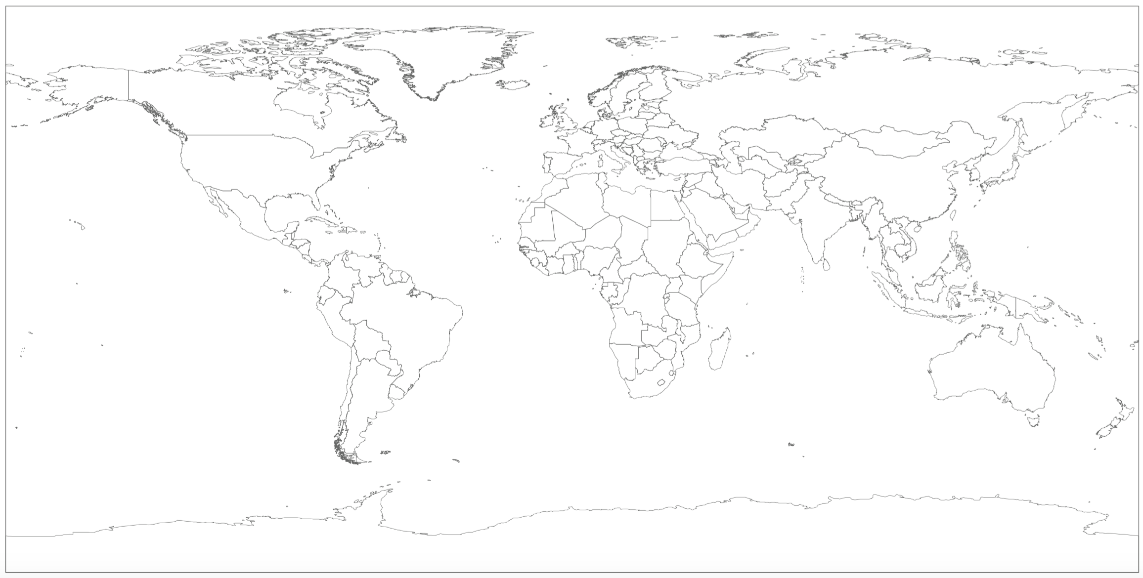
Into this:

Where choice of assembler is concerned, I decided upon Merlin (specifically Merlin Pro, which supported ProDOS). Merlin actually survived into the IIGS era, and is highly capable. I’ve also had great luck scripting it with my Apple II emulator of choice, Virtual ][ (shout out to Gerard Putter, who provides excellent technical support!). With one key combination, I can essentially assemble, save the object file to disk, save the source code to disk, reboot, and run my code. With another key combination, I reboot into Merlin and reload the source code. What our friends developing Apple II software in the 80s wouldn’t have given for that! As an added bonus, I have a full debugger in Virtual ][ that lets me set breakpoints, inspect registers, watch memory locations, et cetera. Legit.
Progress in writing the code to load and display the map on-screen proceeds. I had a little misunderstanding when it came to how the pixels get interleaved between Main and Aux memory, resulting in a bunch of work getting trashed, but back on track after finding some clearer documentation. I would probably be done by now, but I am doing some things in a more generalized manner than strictly necessary, in case I want to reuse any of this code later.

No, TAY doesn't stand for Taylor Swift. I'd be ok if it did, though.
Essentially, I’m writing a generic loader for regular BMP files of double hires resolution. This is something that I haven’t really come across before as again, most of the image loaders deal with files that had the necessary memory interleaving happen at the time of saving. Also, double hires graphics just wasn’t that popular to begin with. For example, BSAVE/BLOAD for double hires graphics is not nearly as standardized as it is for regular hires graphics, with some formats using a single file and others using two.
When it comes to design of the transputer hardware interface, I’ve made progress but less than I have on the software front. It’s interesting, because transputers themselves communicate with the outside world (and perhaps more significantly, each other) using serial links running at speeds from 5 to 20 Mbps. These links are a nice piece of engineering on the part of INMOS, but there’s not much else out there that uses the standard. However, while the links are actually part of the transputer silicon, INMOS also made a couple link adapter chips to interface with other circuits.
 Imagine that, no Eagle parts libraries out there for INMOS Link Adapters. Quickly remedied.
The link adapter chip I’m working with is the IMSC011. It has two operating modes, one a simple parallel interface with a two-wire handshake, and another intended for use with microprocessor buses that map peripherals to memory. While the first mode will come into play when designing circuitry to control the project’s Panaplex and VFD displays, it’s the second that will be used to interface with the Apple II’s bus. I’m currently working on drawing up this circuit in Eagle, my preferred PCB and schematic design software. It’s a lot of fun, and the address line decoding stuff will be a good refresher for when it comes time to build the 8088-based SBC for the Soviet side of the project that calculates doppler shifts and points the antennas.
So there’s where I’m at with the project, namely the graphic display of the satellite’s position. I’ve been working on several other fronts, having re-started the port of the SGP models from clean C++ code among other things, so I have a lot more updates to write. One thing in particular that I want to write up is how I configured Eclipse on Mac to write, compile, and run code using the INMOS DOS tools and WINE. I figure others might benefit, but I also need to document it for my own good in case I ever want to set it up again! So look for that update and more in the near future, I’ll try not to take so long between updates next time :)
Discussions
Become a Hackaday.io Member
Create an account to leave a comment. Already have an account? Log In.