 Jarred
Omnibotler is a reimagination of the opulent, 1980's anthropomorphized omnibot with modern boards and extraneous functionality. This project attempts to retain the aesthetic of the original robot, while adding a functional camera, visor tilt, distance sensors, a refreshed control board, thermal printer, and a pump for water or scotch (its a question of what to water).
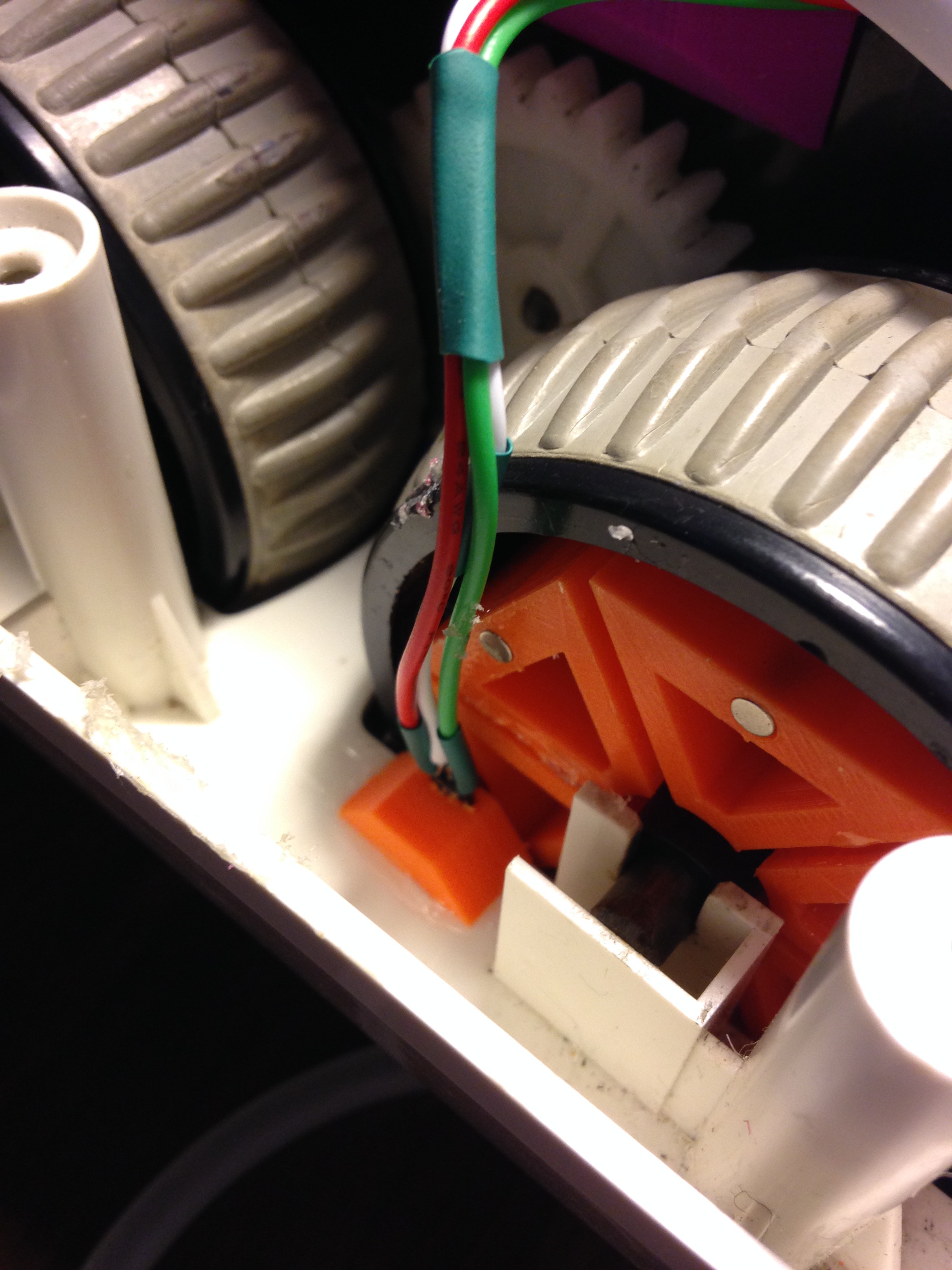
The original omnibot was completed gutted with the exception of the drive system. Replacement parts were designed in 123D design to match existing parts, and provide internal structure.
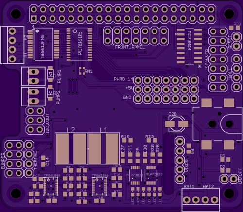
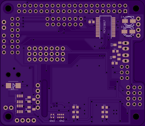
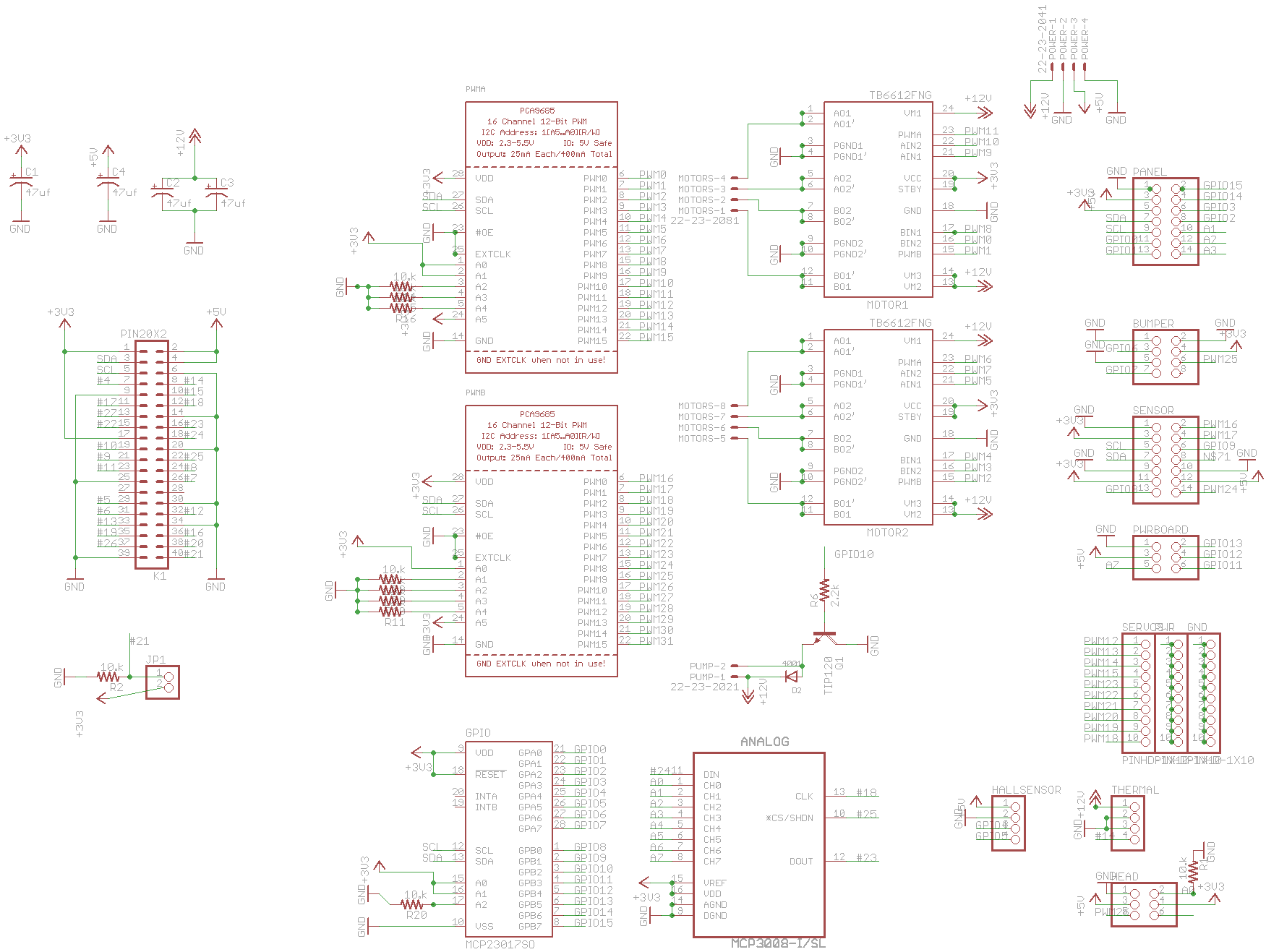
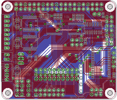
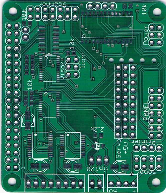
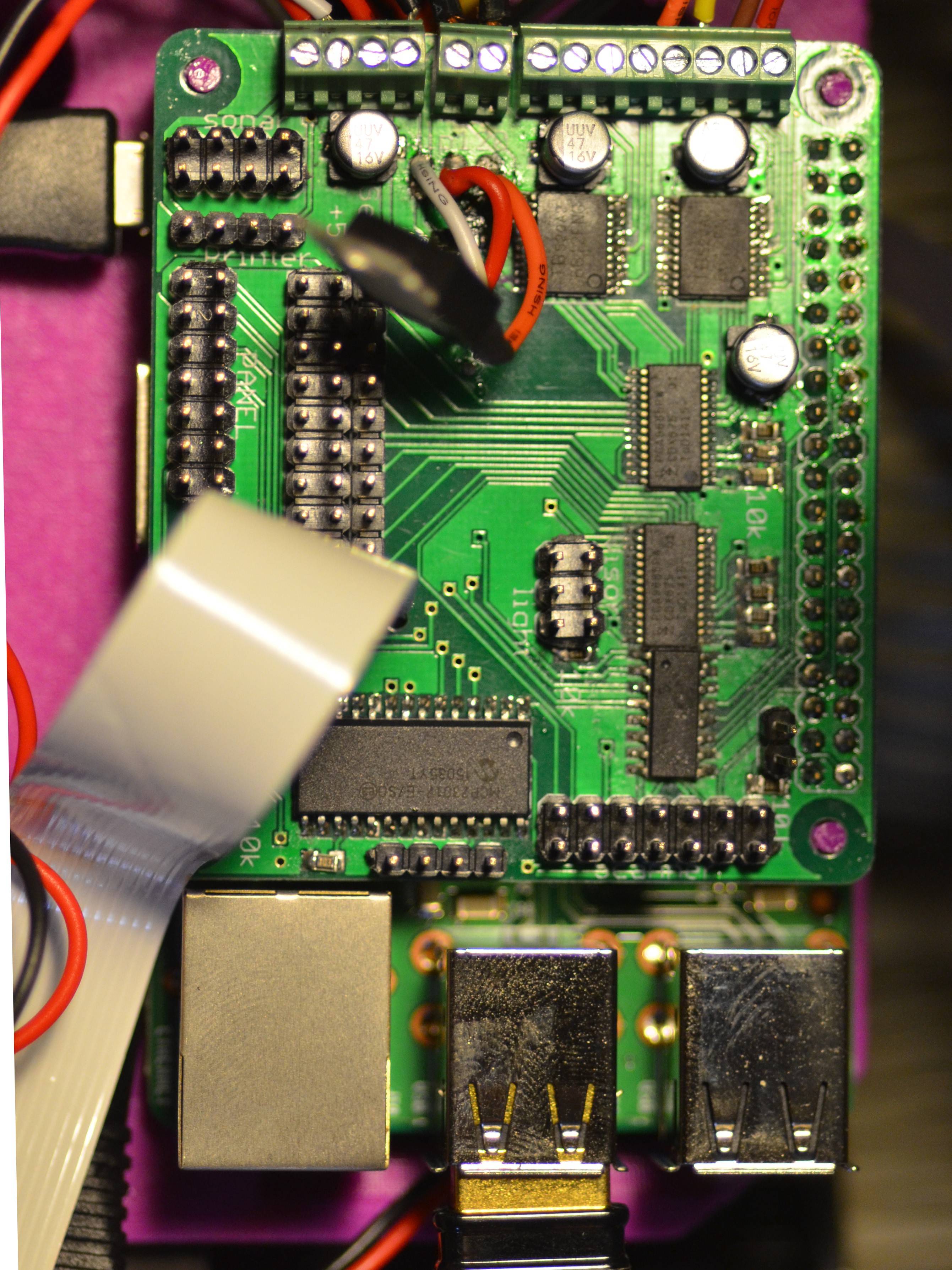
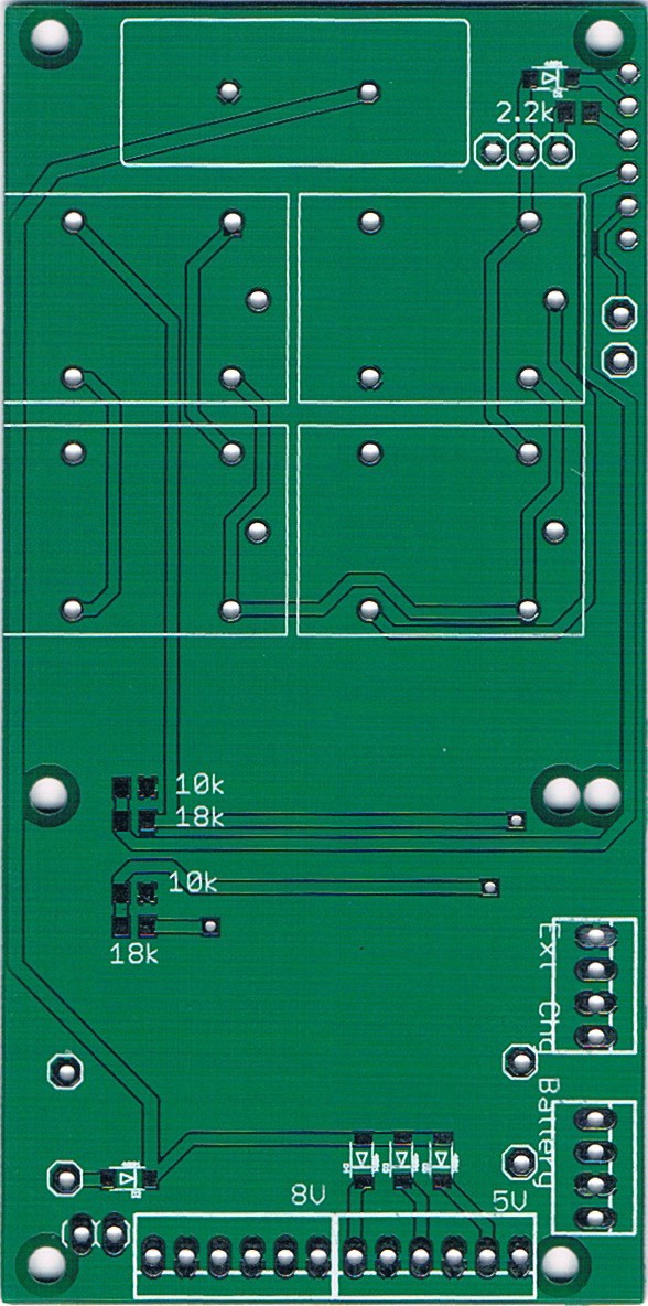
Omnibotler runs on a raspberry pi 2 with a custom hat, and borrows heavily from Adafruit libraries.
No function has been established for the large center bay (previously the tap deck). Possibilities include retracting micro-quadcopter bay or video screen. Additionally, motorized function needs to be added to the arms.
The future goals of omnibotler include serving as the controller of a home automation system, putting a retro tangible face to modern systems.
Project logs will be broken down into discrete areas:
- Raspberry Pi Hat
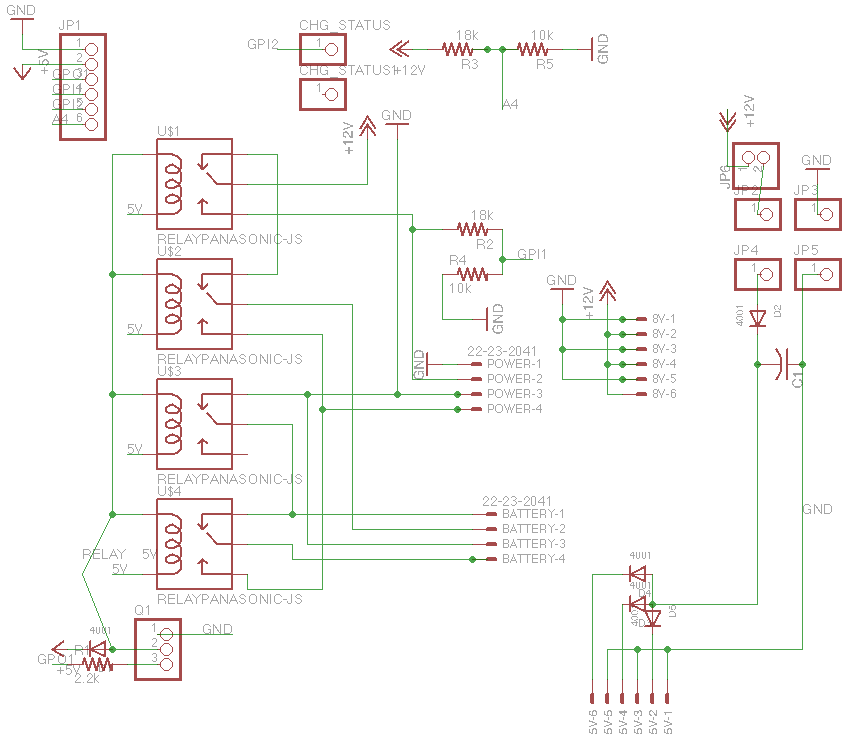
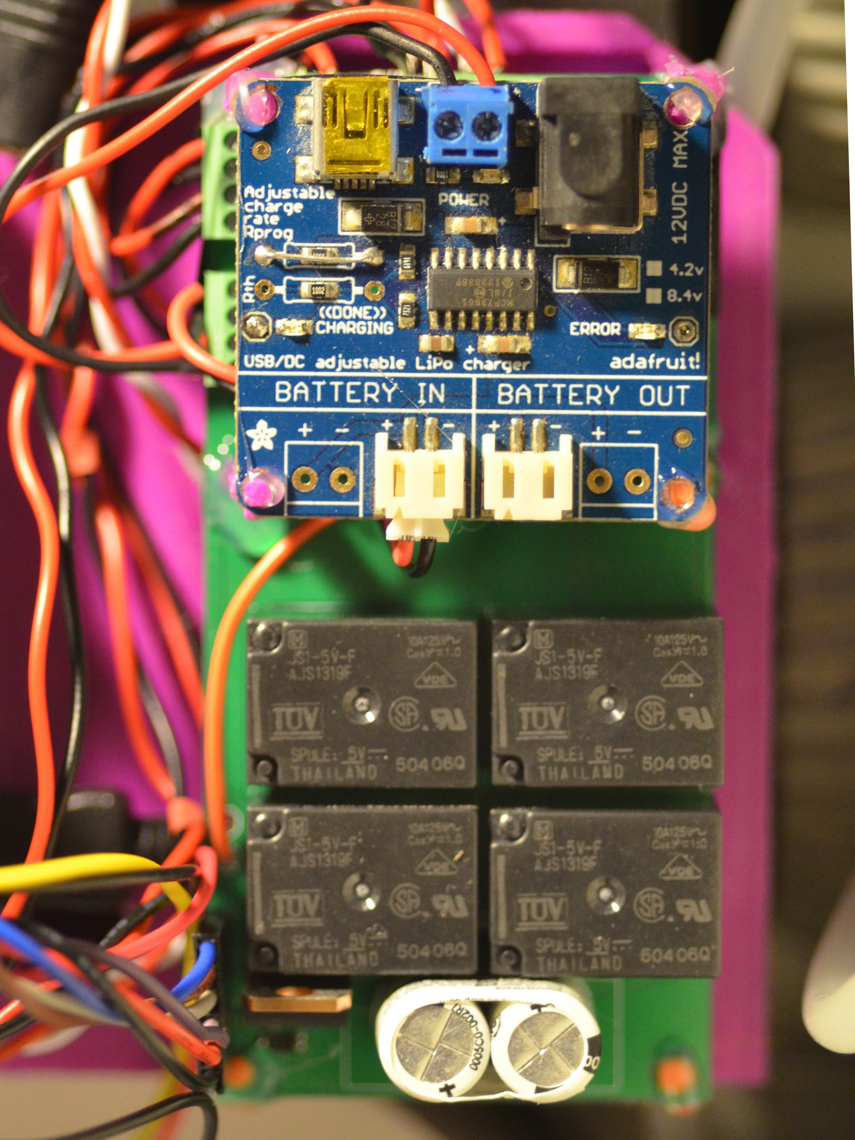
- Power System
- 3D printed
- Avoidance System
- Mapping System
- Front Panel
- Pump
- Thermal Printer
- Code
 Frank
Frank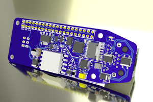
 julien
 Bash Sarbora
really awesome project! Im trying to do something similar and id love to have a look at your code. The listed github links 404, is there somewhere else the files are hosted?