Happy Vertical People Transporter
Douglas Adams envisioned a Happy Vertical People Transporter as opposed to the mundane every day elevators
Douglas Adams envisioned a Happy Vertical People Transporter as opposed to the mundane every day elevators
To make the experience fit your profile, pick a username and tell us what interests you.
We found and based on your interests.
TODO aka future improvements
Somewhere within the following couple of years the project will be rebuilt with better materials to form a nice conversation piece. The elevator will also be equiped with a sound source to recreate some of the conversations the HVPT has with passengers, and a display to show the floor number where the HVPT finds itself.
The Defocused Computer Perception module will also be heavily improved on. Currently it can only track one object (person) and will (with a very high rate) mistake coming passengers for passengers walking away from the elevator, and vice versa.
I have however learned that computer vision is easier to get started with than anticipated, but it is something that I will have to put much more time into for future projects as there is so much more to learn!
The Defocused Computer Perception (DCP) module is used to 1) detect motion on each floor and 2) determine if the motion is coming towards the HVPT or moving away.
OpenCV2 is used with python bindings to make this work. First three images are read, thresholded and then filtered to decide if enough change is present in them to mark it as motion. Thereafter we calculated the moments of the change (in all fairness, OpenCV calculated it, we just asked nicely). If the moment is large enough, we find the centre point and mark it on the original image (it just looks much better than using the thresholded images). Next the absolute distance between a set point and the moment centerpoint is calculated (thanx Pythagoras). As each frame will not neccesarily show forward motion as the person is walking (shadows, arms swinging etc will muck this up) a list is kept and the tendency is calculated (somewhat ineffective though). This lets the Arduino know via serial when movement is detected approaching the HVPT. All of this is iterated frame for frame over each camera to detect motion on multiple levels by utilising only one script. Obviously in a large building this will need to be improved on by using threads, interrupts and maybe more processing power.
And with this, we mark the end of the HVPT project for the Sci-Fi competition. We will however continue this project later on to round it off way better than it is now, and a spin-off is coming in the form of a yard security monitor OR a pool safety monitor. Who knows, maybe both.
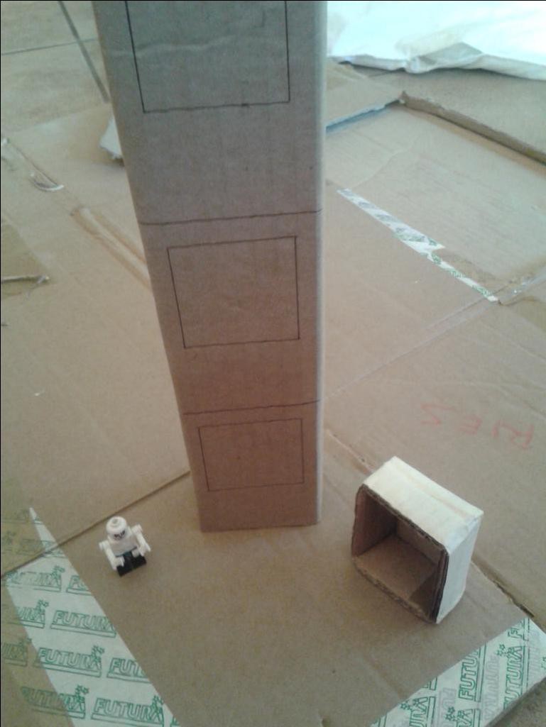
Lolla's part of this project was to build the actual HVPT. Since the first version is more of a proof of concept, most the construction was made out of cardboard box since we had a lot of that lying around. The lift body was constructed out of cardboard with an aluminium foil backing. This backing will later form part of the level detection.
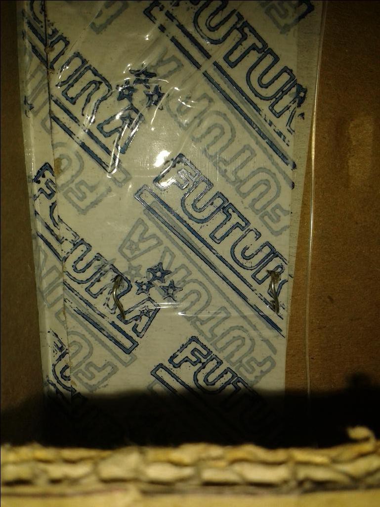
The elevator shaft was also constructed from cardboard box, and 680 ohm resistors were placed in pairs to form a resistor ladder. You can see in the pic below how the legs protruded to make contact with the aluminium foil backing when the lift body moves to a level. The resistors were soldered into a series connection, making two rows of resistors, one down each side. In theory, the 5V will be put over the the complete resistor ladder as well as one extra resistor, effectively creating a voltage divider between the ladder and the referance resistor. All resistors being 680 ohm. Why 680? Well, we had lots of them, so they won the opportunity :)

As the lift body moves past a pair of resistors, they form part of the voltage divider, and thus the Arduino's ADC can determine the current level. The contact points were made on the bottom of each level. In retrospect, halfway might have been better, but I will leave this for DigiGram to fix with code.

What started out as a simple idea turned into some head scratching. I did not want to order any parts for this build, so IR and ultrasonic sensors were out of the question. I decided to use a resistor ladder to determine the current lift (elevator) level, as shortly described by [Lolla] in the build log: build.
Since the resistor contacts are at the low side of each level, I will have to determine three cases.
1) If no level is detected, assume the lift is between levels and report the previous value
2) If the lift is moving downwards, move until the correct level.
3) If the lift is moving upwards, move until the correct level, then move until the level changes, then move slightly down again.
This is not ideal, and if we had the time, I would have changed the layout, but I'm back in West Africa for work, so had to finalise everything sooner.
ADC values were calculated for the different floors, and then approximated experimentally:
Calculated | Experimental
0: 682.7 | 670
1: 819.2 | 803
2: 877.7 | 860
Ranges were defined around these values to catch slight off readings as well.
Code looks something like this:
currentFloorRes = analogRead(levelPin);
if (currentFloorRes > 640 && currentFloorRes < 735){currentFloor = 0;
}
else if (currentFloorRes > 735 && currentFloorRes < 830){currentFloor = 1;
}
else if (currentFloorRes > 830 && currentFloorRes < 900){currentFloor = 2;
}
else { currentFloor = 0;}floorDisplay(currentFloor, destFloor);
I'm really starting to like FreeCAD. Sadly my build (0.14 on Ubuntu, daily on 19 March 2014) still has no Assembly support, so all is built on one set that can't be moved. But different "layers" can be hidden to show the internals. Not that there are many. The shaft will get a resistor ladder and a Cu or Al foil backing on the elevator to calculate position. This is not the best way to do it, but one of my goals were to use only parts I have or can scavange. And I don't have rangefinders or 3 IR trip beams that I can use for this project right now.
A few LED's might be added for decoration, and a display above the elevator doors will be added to show the current level the elevator is at. Maybe 7-segment, or due to space maybe a simple LED bar. Will see about that when I get to play with my components again.
This will be built out of 3mm hardboard or something like it. My CNC won't be built by the deadline, so hand tools here we come.
Lastly, the "winch" spool will be a bobbin or similar scavenged from a seamstress and glued to the motor. Almost any thread should be strong enough for this light weight elevator, but a commercial product will need to abide to stricter safety guidelines.
If a picture paints a 1'000 words, a STL must be 1'000'000 words then right?
FreeCAD file is available here
My previous attempts at computer vision was all done in Python with numpy. With arrays I detected movement (very poorly) and distance with a laser and some trigonometry. This time I wanted to try and figure out openCV. Turned out to be so easy! The basic gist of the Defocused Computer Perception [DCP] is as follows:
> Read all connected webcams in a loop //Currently only one is read
> Compare successive images. If movement is detected (and above threshold), figure the center of the movement
> Apply a crosshair or circle to the point to show on display where movement was detected
> Next call the HVPT to the floor where movement was deteced.
> The crosshair will be redrawn for all movement, but the call command will only be issued once per passenger.
> The crosshair is not really needed, but it does give the system an AI feeling.
> If time allowes, the movement might be used to detect if someone is walking to or from the HVPT. Or if a second passenger is spotted, the HVPT can wait for them, or speed up to save the first passenger from unneccesary chit chat.
> For every 42nd passenger, the HVPT gets a psycotic breakdown and need to go to the basement for councelling (where Marvin awaits for 500 years). The breakdowns are real in the books, the basement is my spin on it.
> This quote is extremely important to remember when you do encounter bugs (or abnormalities as I call them) in the code from the book series: "their fundamental design flaws are completely hidden by their superficial design flaws"
Alpha code can be found here: DigiGram GitHub
Our goals for this project is
Create an account to leave a comment. Already have an account? Log In.
Become a member to follow this project and never miss any updates

 Daniel Domínguez
 Inderpreet Singh
 Myrijam
 shlonkin
I love the project and anything cardboard :-) Douglas Adams had a lot of neat ideas :-)