 b.kainka
I used Basom to program the Tiny13. The source is so short I can show it here. I used an integration time of 10 µs. At the beginning I collect a reference value Ref to know the LED voltage without signal. This is used later to detect the voltage loss caused by an RF signal.
Bas and HEX files: http://www.elektronik-labor.de/AVR/Sparrow/SparrowRX.html
Cheepit upload via Sound: http://tiny.systems/categorie/cheepit/RFDetector.html
Video:
The project goes on. Leander made a simple transmitter: The ATtiny13 generates an RF signal around 300 kHz and is tuned to match the LC circuit. A second LC circuit receives the RF energy. He also built a simple data link using two coils with hardly any additional components on the Tiny13.
'ATtiny13 RF receiver
$regfile = "attiny13.dat"
$crystal = 1200000
$hwstack = 8
$swstack = 4
$framesize = 4
Config Portb = &B000000010
Dim T As Byte
Dim N As Byte
Dim D As Word
Dim Ref As Word
Dim Diff As Word
Config Adc = Single , Prescaler = Auto
Config Timer0 = Pwm , Prescale = 8 , Compare B Pwm = Clear Up
D = 0
For N = 1 To 20
Portb.3 = 1
Portb.3 = 0
Waitus 10'integration time
D = D + Getadc(3)'LED2 voltage
Next N
Ref = D / 20
Do
Portb.3 = 1
Portb.3 = 0
Waitus 10'integration time
D = Getadc(3)'LED2 voltage
If D >= Ref Then
Pwm0b = 0
Else
Diff = Ref - D
If Diff > 2 Then
Pwm0b = 128'sound and LED1
Waitms 50
End If
End If
Loop
End


 Hulk
Hulk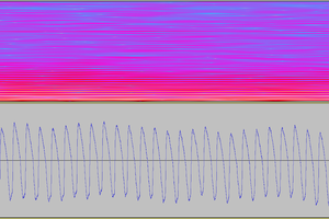
 Marek Materzok
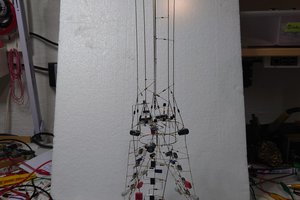
 MaBe42
 jurc192
The complete schematic of the Sparrow can be seen here:
http://www.elektronik-labor.de/AVR/Soundprog6.html#v2
Actually you need only the Tony13 plus LEDs like in the schematic above. The switches are not in use. But I added a sound transducer at B1 with 1k in series to keep Vcc quiet.