 Linus Dillon
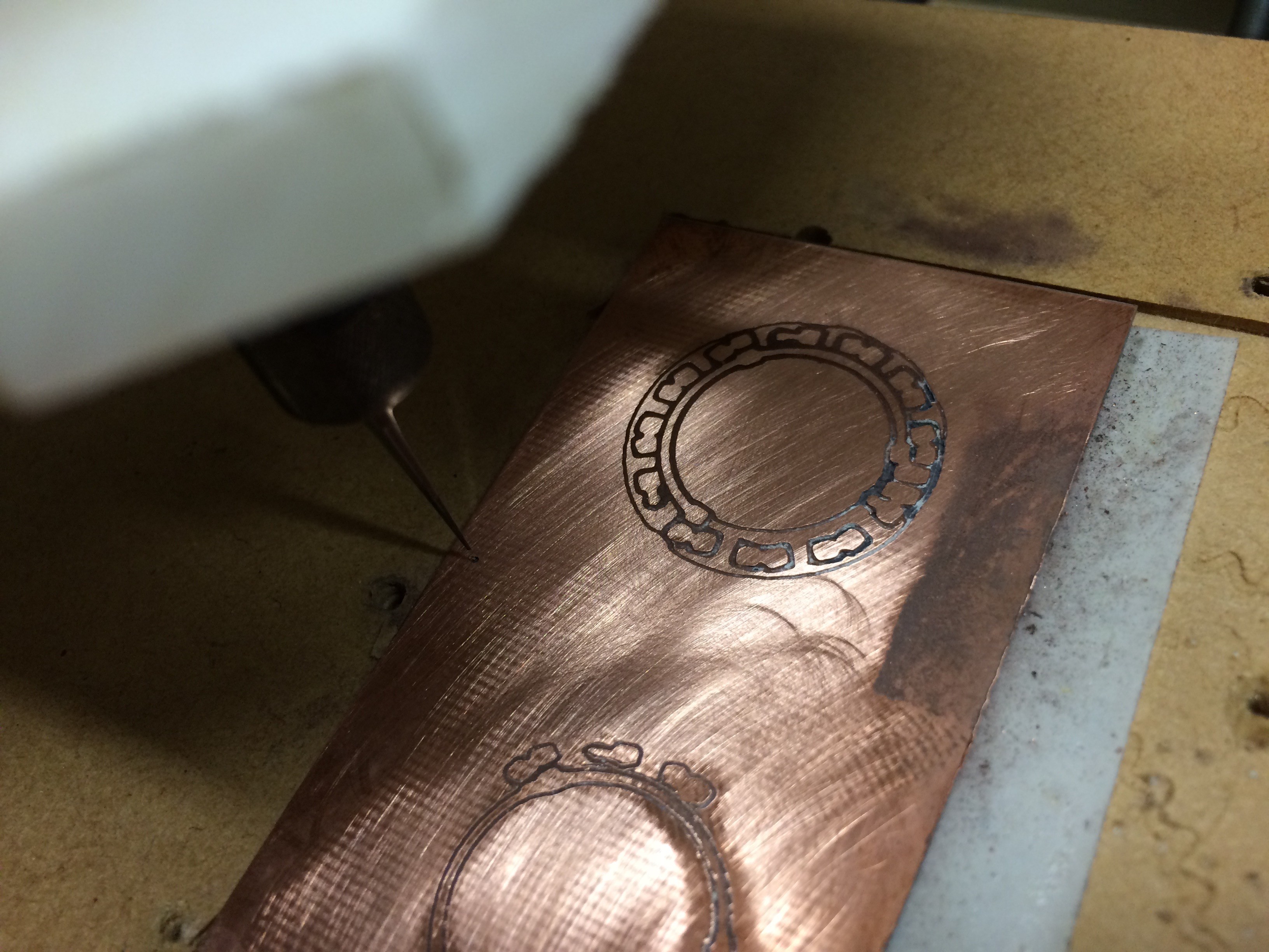
This project is largely a way for me to ease into SMD design and assembly. I'm moving to SMD for some of my other projects (#Insulin Minder MK2, others) which would use custom PCBs and SMD components. Will be trying a few things here to see what works well (milling a PCM at home, getting one made by a PCB service, hand-soldering SMD components, solder paste + hot air rework). No ICs in this one, but its a start. Plus will hopefully end up with a useful add-on for my soldering iron.
0%
0%
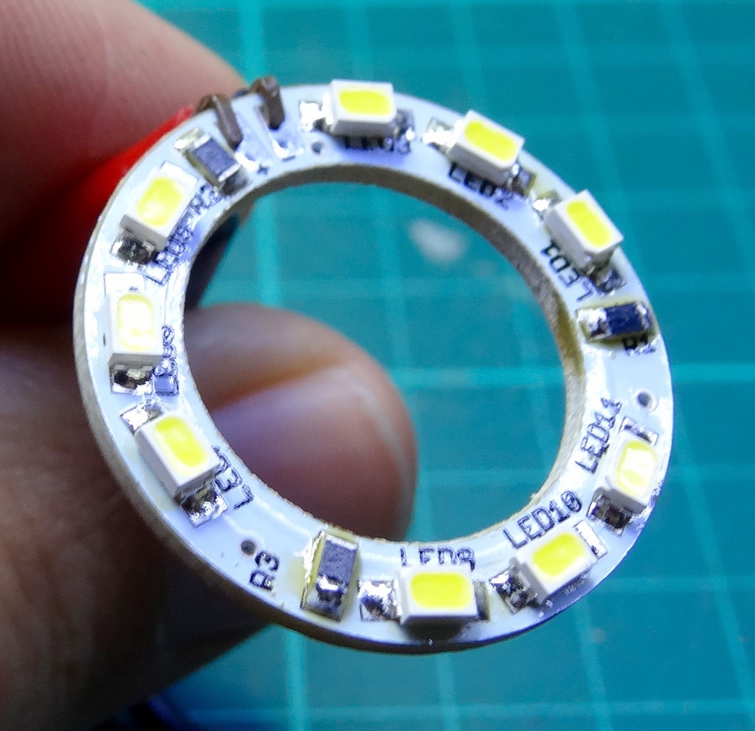
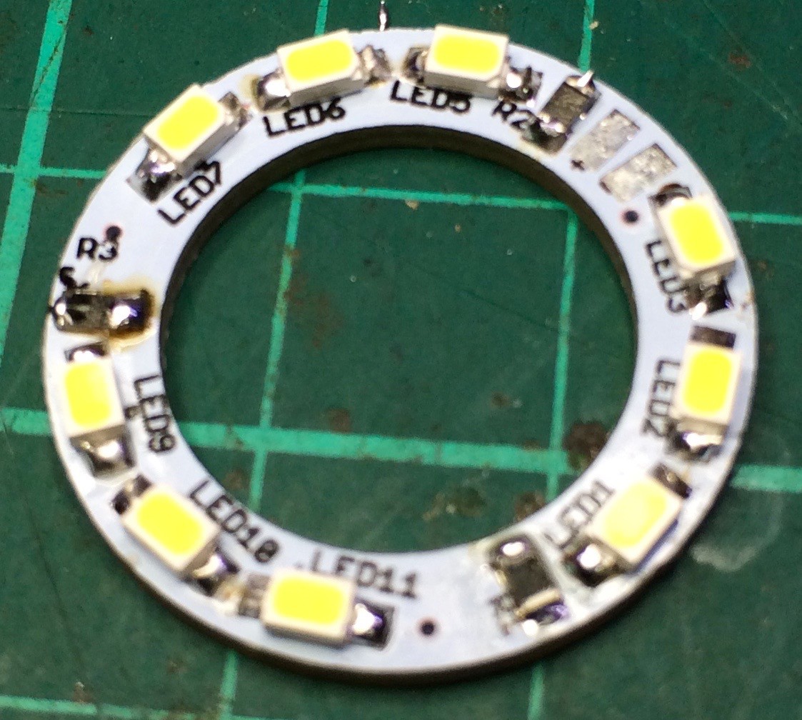
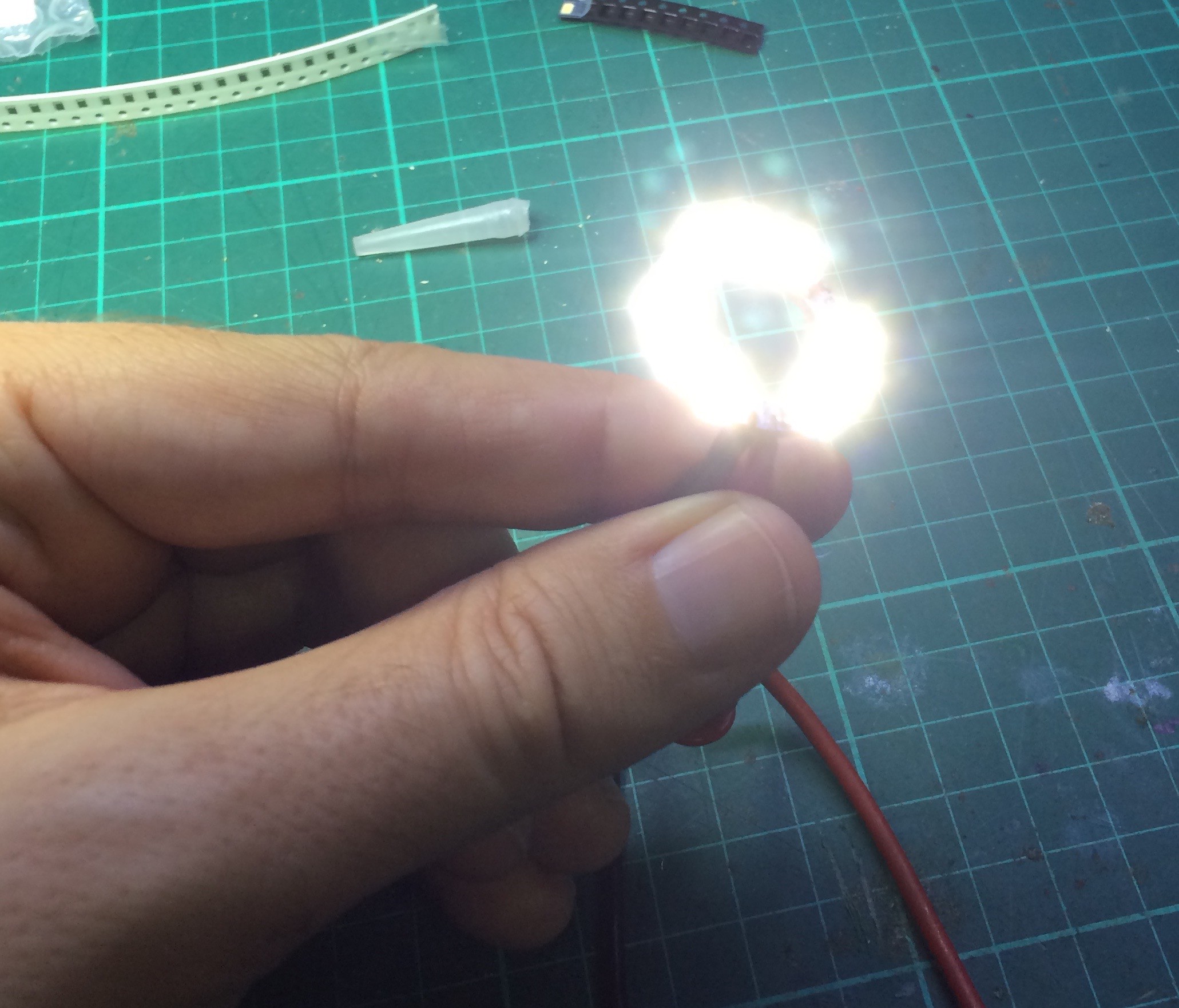
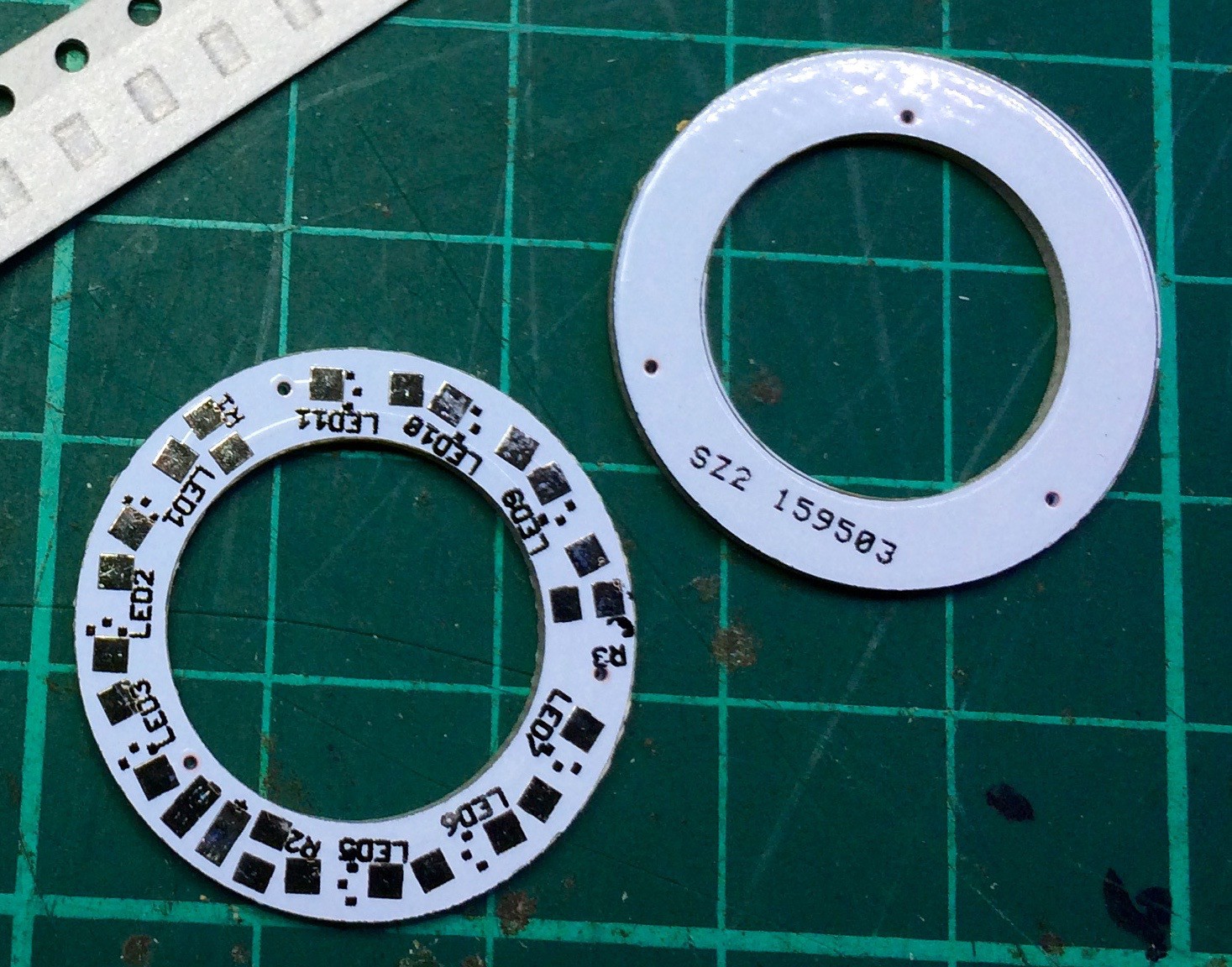
Soldering Iron Ring Light
Light integrated into soldering iron to illuminate what I'm soldering, and learn a bit about SMD design and getting PCBs made
Become a Hackaday.io member
Already have an account? Log in.
Just one more thing
To make the experience fit your profile, pick a username and tell us what interests you.
Pick an awesome username
hackaday.io/
Your profile's URL: hackaday.io/username. Max 25 alphanumeric characters.
Pick a few interests
Projects that share your interests
People that share your interests


 zakqwy
 Christoph
 Timo Birnschein
This could be a cheap ringlight for a pocket camera too!